
Wrestling with the Noise: What I Learned About Radio-Frequency Interference
Reflections on Chapter 15 of Al Penney’s RAC Basic Course

Anyone who has spent time on the air will eventually run head-first into radio-frequency interference (RFI)—and usually at the worst possible time. You finally settle into a good QSO, or you’re testing a new antenna, and suddenly the bands dissolve into a wall of buzz, crackle, or inexplicable signals that have no business being there.
For me, these problems are more than just an occasional amateur-radio annoyance—they echo challenges I’ve dealt with for decades in my professional life. My work in machinery safety involves electromagnetic compatibility (EMC) testing, troubleshooting, and ensuring compliance with a wide range of functional-safety standards. In the world of machinery, poorly controlled electromagnetic phenomena can have far more serious consequences than a ruined QSO: they can shut down production lines, disable safety-related parts of control systems, or jeopardize the performance of SIL-rated and PL-rated safety functions. Understanding how interference couples, propagates, and affects equipment has been part of my daily toolkit for years.
So when Al Penney covered RFI and EMI in the RAC Basic course yesterday [1], it felt like familiar territory—but with a distinctly amateur-radio flavour. The chapter blended physics, practical engineering, and station-craft in a way that resonated deeply with my EMC experience. As someone who cares about both signal integrity and functional safety, this was immensely satisfying—and a potent reminder that good EMC practices are universal, whether you’re safeguarding a press-brake control system or keeping an HF rig clean on 20 metres.
Below are my takeaways, with plenty of technical depth for those who enjoy understanding the “why” behind the “what,” and hopefully helpful guidance for newcomers wrestling with their first tangle of interference.
The Two-Sided Nature of RFI
Al broke the entire problem down into two buckets:
- Interference your station causes to others
- Interference caused to your station by other devices
The most sobering part? Most cases of interference can be cured, but almost never by arguing about blame. You have to consider both the equipment and the humans involved. Al’s reminder to approach every RFI complaint with “calm, empathy, and cooperation” should be etched on every ham’s shack wall.
RFI vs EMI: Getting Our Terms Straight

We often throw “noise” around as a catch-all term, but the distinctions matter.
- Radio-Frequency Interference (RFI) is interference in a receiver caused by unwanted signals (only one of which is desired).
- Electromagnetic Interference (EMI) is RF energy that affects equipment not intended to receive RF, such as machinery, appliances, furnaces, smoke detectors, thermostats, speakers, telephones, and computers.
When RF bullies its way into the front end of a device through inadequate shielding or filtering, you get EMI.
It’s also worthwhile remembering that, depending on the source you read, RF is the Extremely Low Frequency (ELF) band, which is defined as ranging from 3 to 30 Hz by the International Telecommunication Union (ITU) and other major standards bodies, with corresponding wavelengths from 100,000 km down to 10,000 km. However, Very Low Frequency is the lower end of the RF spectrum and the range used by practical radio transmission systems, spanning 3 kHz to 30 kHz. Happily, none of these frequencies are included in the amateur bands.
Four Core Types of Interference
Al identified four primary mechanisms that create RFI/EMI problems:
1. Noise
External noise from electrical systems—motors, switching supplies, furnace igniters, fluorescent lighting, thermostats, dimmers—creating broad-spectrum buzzes and raspy signatures across HF.
These often show up as wideband trash rather than discrete signals. Identification usually means turning things off one by one until the culprit reveals itself. Al suggested that you can start by turning off the main switch in your home to see if the noise disappears. If so, you have to go through each circuit in your home to find the culprit.
2. Fundamental Overload (FO)
This is one of the most common problems. Fundamental overload (FO) occurs when a strong RF signal overwhelms the receiver’s front end, which lacks sufficient filtering.
It’s fascinating how stark the physics are. The strength of the interfering signal follows the inverse-square law, modelled as:

Where
I = field intensity
d = distance from the source

If you consider a sphere surrounding the point source in the diagram above, the area of the inside of the sphere is defined by

Where:
- S(r) = power flux density at distance r (W/m²)
- PTX = RF power delivered to the antenna (W)
- G = antenna gain referenced to an isotropic radiator (dimensionless, not in dBi)
At radius r from the source, a certain intensity exists on the surface of the sphere, I, which is measured in volts per metre (V/m). At 2r, the intensity according to the formula above is now 1/4I, and at 3r it falls to 1/9r. Even doubling the distance between two houses can reduce the interfering field strength to one-quarter. Of course, moving your neighbour’s house farther away from your antenna may be difficult, so it’s likely easier to move your antenna 😀.
3. Cross Modulation (XM)
Cross modulation (XM) occurs when a strong AM-type signal is rectified at some stage of a receiver, imposing its modulation on another signal.
This is most noticeable on AM broadcast receivers, but the presentation reminded me of the old NTSC TV days, when strong local signals produced ghosting artifacts.
4. Intermodulation Distortion (IMD)
Intermodulation distortion (IMD) is the mixing of two or more signals in a nonlinear device, producing sum and difference frequencies:

A common nuisance is the third-order IMD:

These often fall near the desired signal and can be nearly impossible to filter out, especially in dense RF environments like 2 m FM repeaters downtown.
Spurious Emissions: When the Transmitter Misbehaves
Even well-designed transmitters generate small amounts of harmonics and other spurious emissions.
Harmonics occur at integer multiples of the fundamental:

Where
f0 = operating frequency
n = harmonic number
The 2nd and 3rd harmonics are typically the strongest.
Good transmitter design—combined with proper station grounding and not over-driving an amplifier—keeps these suppressed well below regulatory limits.
The Role of the Source–Path–Victim Model
One of the most elegant conceptual tools in the chapter is the source–path–victim model.
Every EMI problem requires:
- A source of RF energy
- A path (radiated, conducted, or induced)
- A victim device susceptible to that energy

Radiation Coupling
Radiation coupling is the form of RFI most amateurs and engineers encounter: electromagnetic energy simply travels through free space from the source to the victim device. Because it doesn’t rely on any physical connection, it can affect equipment over surprisingly long distances, especially in RF-dense environments such as industrial plants, telecom sites, hospitals, or any setting where multiple transmitters and sensitive receivers share the same airspace.
Conduction Coupling
Conduction coupling occurs when unwanted RF energy hitches a ride along conductive paths—power wiring, signal lines, control cables, grounding conductors, or any metal that forms a continuous path between the source and the affected device. This is a common issue in machinery and building wiring, where poor cable management, inadequate bonding, or inconsistent shielding allow interference to propagate directly into sensitive electronics. Good grounding practice, proper cable segregation, and high-quality shield terminations are essential tools for controlling conducted RFI.
Capacitive Coupling
Capacitive coupling occurs when an electric field from an interference source induces charge to flow into an adjacent conductor or circuit. This mechanism becomes especially troublesome when components or cables are routed close together—such as neighbouring PCB traces, bundles of control wiring, or harnesses inside industrial enclosures. Thoughtful layout, appropriate separation, and maintaining proper insulation or shielding significantly reduce the risk of RFI coupling through stray capacitance.
Magnetic Coupling
Magnetic (inductive) coupling occurs when a varying magnetic field induces voltage into nearby conductors, particularly loops or long parallel runs. This is the mechanism behind many audio rectification problems, transformer hum issues, and interference in industrial control circuits. Twisted-pair cabling, increased spacing, minimizing loop area, and adding magnetic shielding are proven strategies to limit inductive coupling and maintain the integrity of both communication and safety-related signals.
Real-world problems
Most real-world problems involve multiple paths. For example:
- RF radiates from your antenna
- It couples into your neighbour’s speaker wires
- The wires conduct it into a cheap audio amplifier
- A transistor rectifies the RF and produces audible audio
Until you identify the correct path, you’re just throwing ferrites into the void.
Differential Mode vs Common Mode: Why Ferrites Work (or Don’t)
The distinction between differential-mode (DM) and common-mode (CM) currents is key to understanding how to solve interference problems.
- DM currents flow out on one conductor and back into the other.
- Filters solve DM.
- CM currents appear equally on multiple conductors and typically return via ground.
- Ferrite chokes solve CM.
A single filter type cannot fix both. Many new hams attack CM problems with DM filters and end up frustrated.
Cleaning Your Own House First

One of the most important practical lessons: before helping anyone else with RFI, make sure your own station is clean.
- Tighten every connector
- Bond the equipment to a single-point ground
- Add a low-pass filter (LPF) on HF transmitters
- Ensure proper coaxial routing and no sharp bends
- Avoid over-driving microphones or amplifiers
- Keep a tidy, professional-looking station (this is diplomacy!)
Nothing inspires confidence like demonstrating your own trouble-free system.
Filters, Ferrites, and Other Tools in the RFI Toolkit
Low-Pass Filters (LPF)
Used on HF transmitters to block harmonics above the cutoff frequency.
High-Pass Filters (HPF)
Useful for TV interference, passing UHF/VHF while attenuating HF and strong low-frequency fundamentals.
Band-Pass, Band-Reject, and Notch Filters
Situational, but powerful when eliminating narrow interference bands.
Quarter-Wave Stub Filters
These are elegant and surprisingly effective. Their length is given by:

Where
c = speed of light
f = frequency
Vf = velocity factor of the cable
They create a deep notch at the design frequency and weaker notches at odd harmonics.
Ferrites (the ham’s best friend)
Ferrite chokes suppress common-mode currents on:
- Speaker wires
- HDMI cables
- CATV coax
- USB cables
- Power cords
- Audio interconnects
Ferrites are simple, cheap, and remarkably effective.
TVI, Audio Rectification, and Troubleshooting Strategies
Television interference (TVI) and audio rectification are classic RFI battlegrounds.
Speaker leads are particularly problematic because:
- They’re long
- They’re often resonant on HF
- They connect directly to output transistors
- Negative feedback loops re-inject rectified energy
A simple test: swap the speakers for a pair of short-lead headphones.
If the interference vanishes, ferrites on the speaker wires are almost guaranteed to solve it.
Cable TV: Blessing and Curse
Cable systems should shield against ingress and egress.
In reality, corrosion, bad connectors, and poor workmanship create unintended long wires that pick up RF beautifully.
For CATV interference, the first line of defence is always a common-mode choke on the CATV coax
If that fails, it may be a direct pickup issue inside the TV set—something only the manufacturer can truly fix.
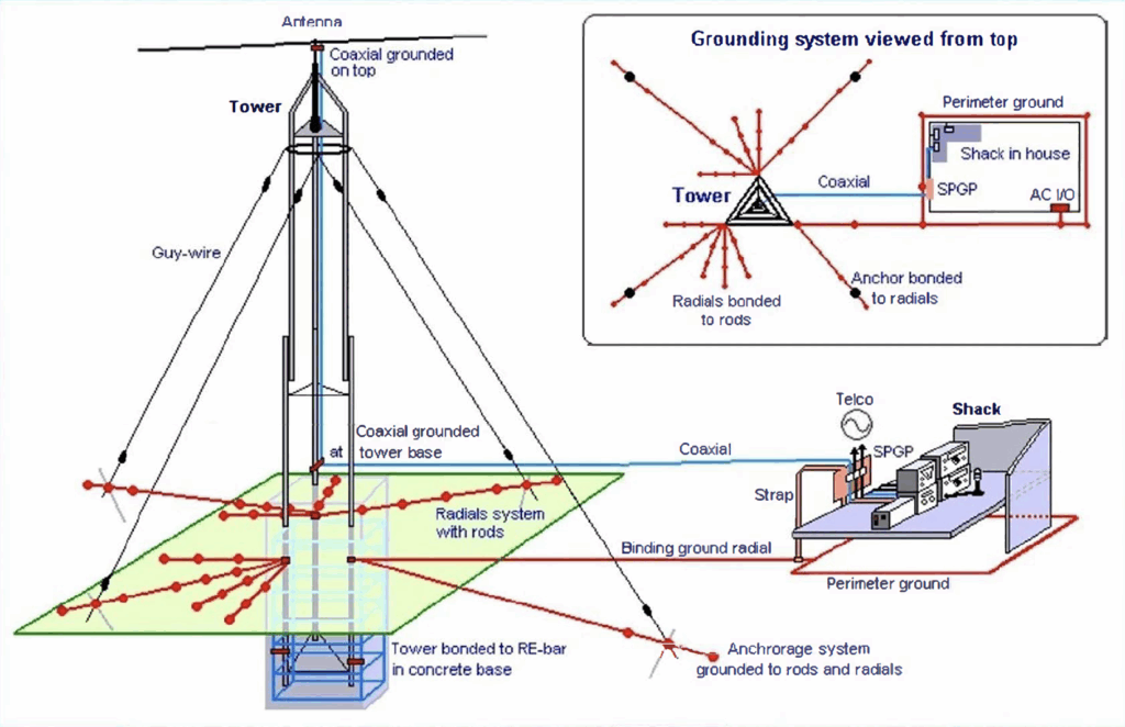
Grounding: A Double-Edged Sword
Grounding is essential for safety and lightning protection, but long RF grounds—especially at VHF or UHF—can turn into magnificent radiators.
A “ground” that’s several wavelengths long is just an antenna with a superiority complex.
The key is single-point bonding and keeping ground lengths as short as practical.

image: Ward Silver [5]

Dealing with Neighbours: The Human Side

Al spent a surprising amount of time on interpersonal skills—and rightly so.
When someone complains:
- Stay calm
- Express concern
- Explain the issue in simple terms
- Avoid blaming their equipment
- Offer to test collaboratively
- Never open or modify their gear
If the fault isn’t yours, your role becomes “locator of solutions,” not “provider of unauthorized repairs.”
Done right, you transform from “the guy causing problems” to “the neighbour who helps solve them.”
Final Thoughts
This chapter was one of the best blends of physics, practical engineering, and human communication I’ve encountered in the RAC course so far. RFI isn’t just about circuits—it’s about relationships, systems thinking, and methodical troubleshooting.
As someone who enjoys both the science and the diplomacy of amateur radio, I came away from Al’s session energized and better equipped—not just to solve interference, but to prevent it, understand it, and teach others about it.
And with the RF environment becoming more hostile every year, these skills matter more than ever.
Bibliography
[1] Al Penney, Radio Frequency Interference, RAC Basic Qualification Course, Chapter 15, Radio Amateurs of Canada, 2025.
[2] ‘Types, Uses, and Benefits of RF Shielding’. Accessed: Nov. 18, 2025. [Online]. Available: https://www.iqsdirectory.com/articles/emi-shielding/rf-shielding.html
[3] T. Ellison, ‘Grounding Systems in the Ham Shack – Paradigms, Facts and Fallacies’, Flex Radio. Accessed: Nov. 18, 2025. [Online]. Available: https://helpdesk.flexradio.com/hc/en-us/articles/204779159-Grounding-Systems-in-the-Ham-Shack-Paradigms-Facts-and-Fallacies
[4] ‘Anger as Man Working From Home Demands Neighbors’ Kids Play Inside’, Newsweek. Accessed: Nov. 18, 2025. [Online]. Available: https://www.newsweek.com/anger-man-working-home-demands-neighbors-kids-play-inside-1732472
[5] W. Silver, N0AX, ‘Ham Radio Tech: RF Management–In the Field’, OnAllBands. Accessed: Nov. 24, 2025. [Online]. Available: https://www.onallbands.com/ham-radio-tech-rf-management-in-the-field/
[6] M. Mikelson, KD8DZ, ‘When Lightning Strikes — Grounding for Amateur Radio Stations’, Feb. 25, 2024.
Leave a Reply