Author: Doug Nix

  • Coffee

    Coffee

    Given that this blog’s tagline is …because coffee…, you might think I would have written about this vital fluid long ago. I’ve had other things on my mind besides my favourite beverage. If you’re unclear about what I’ve been thinking about, see my earlier posts about my world travels, in person and via radio, or check out my Now page.

    Early exposure

    Instant coffee granules by Editor at Large – Own work, CC BY-SA 2.5,
    Electric coffee percolator
    by Andreaze – Own work
    CC BY-SA 4.0

    I first started drinking coffee around age 6, in the early 1970s. At the time, my parents drank instant coffee most of the time, and percolated coffee on fancy occasions (a process that almost universally produces abominable brews by boiling and repeatedly recirculating the water).

    1980s drip coffee

    Mr. Coffee Machine
    Agent Palmer’s blog

    High school

    By Mr. Coffee, Public Domain

    Fast forward to high school, when I started drinking drip coffee in the high school cafeteria. Tim Hortons’ coffee became a thing for me (and most of my friends) during those years too. That brew was generally better than the instant coffee I got at home, or even the drip coffee made by the Mr. Coffee machine in nearly every home in the 1970s and 80s.

    Melitta conical coffee filter

    When I started college in 1982, cafeteria coffee and Tim Hortons’ coffee were staples. I also used a manual Melitta filter at home.

    Work exposure

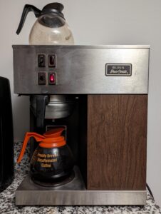
    Bunn Pour-O-Matic machine
    Reddit

    After college, I started my first full-time job and was introduced to the office Bunn coffee machine. For a drip machine, few coffee makers make coffee as uniformly poor. I think part of the problem is the quality of the coffee businesses buy for this purpose. A bigger part is keeping the heat on under the pot all the time. And the heat always seems to be set too high. Anyway, the net result is nasty coffee.

    Caffeinated to the max

    In the early 90s, my caffeine addiction hit new heights. I was drinking 10-12 mugs of drip coffee a day. My employer used Bunn equipment that brewed into large thermal carafes, so the coffee never got that burnt taste the Pour-O-Matic machines imparted. Coffee was free and readily available, and the pressure was high.

    Self-employment brings choice

    Eventually, I started working for myself. With my wife’s help, I weaned myself down to 2-3 8 oz mugs a day. During this time, we started drinking espresso-based drinks. Our first espresso machine was a cheap machine we picked up somewhere; I’m no longer certain of its make or where we got it. You could make coffee with it, but it wasn’t much. It gave us a chance to discover home espresso.

    Breville Infuser

    Eventually, we wore that machine out and replaced it with a Breville Infuser and a Smart Grinder. As an entry-level espresso machine, the Breville Infuser is a great place to start.

    In time, the steam valve seized despite regular descaling, so we had it repaired. Eventually it seized again, and we replaced it with another Infuser. Eventually, we wore out the first Smart Grinder and replaced it with another. The steam valve on the new machine eventually seized, so we sent it to Breville’s service centre for repair. After it came back, it ran well for a while, but then the pressure gauge quit working. I think some mineral scale flaked off where the tubing was disturbed, travelled to the branch leading to the gauge, and blocked it. Eventually the steam valve seized again, and that was it for the Breville era.

    We explored many different coffees during this time and struggled a bit with getting the grind size right. The Breville machines managed shot size by volume and had automatic single- and double-shot programmes. Hot water dispensing was limited to 8 oz, so you couldn’t overfill mugs. Steam production was limited only by the water volume in the tank. Because these machines are semi-automatic, they limit the number of variables; you can adjust only the coffee type, roast, and grind, which limits learning but makes the machines pretty easy to use.

    The Quickmill era

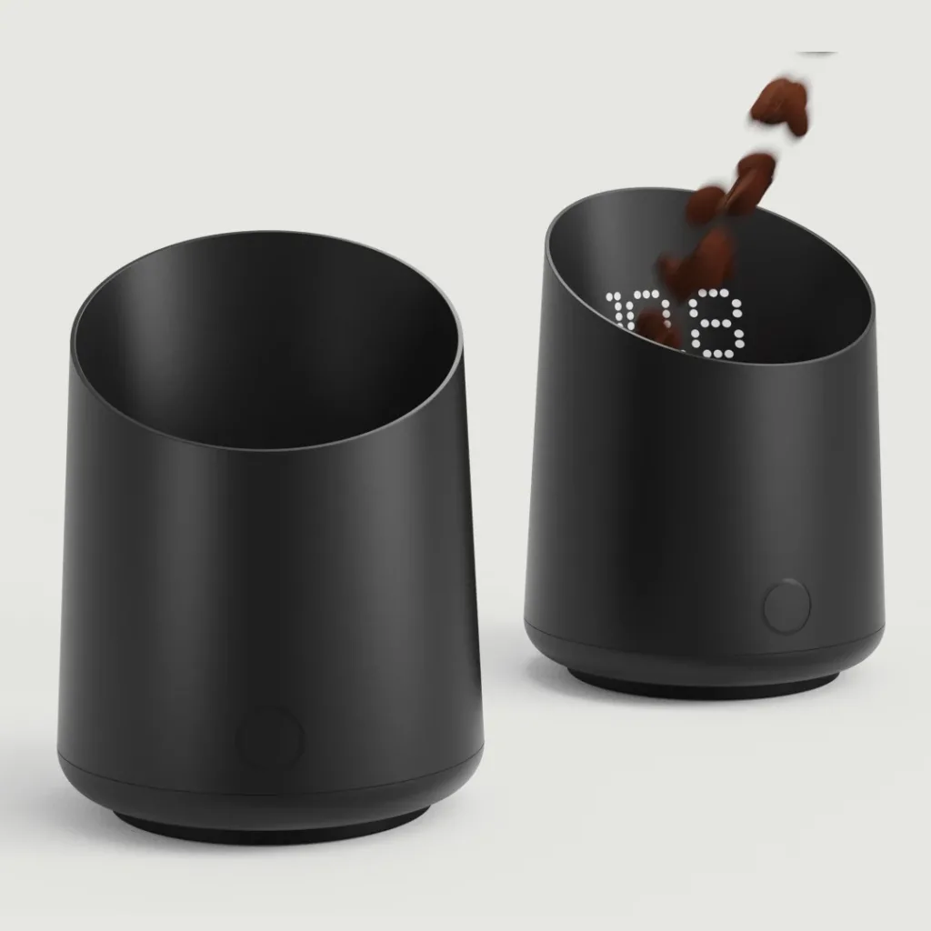
    Two Subminimal Subscale Digital Dosing Cups in matte black, shown against a light grey background. The cylindrical, slightly tapered cups feature integrated digital scales and touch-sensitive buttons. The cup on the right displays a white LED weight reading as coffee beans fall into it, while the cup on the left is empty with its display turned off.
    subminimal Subscale®
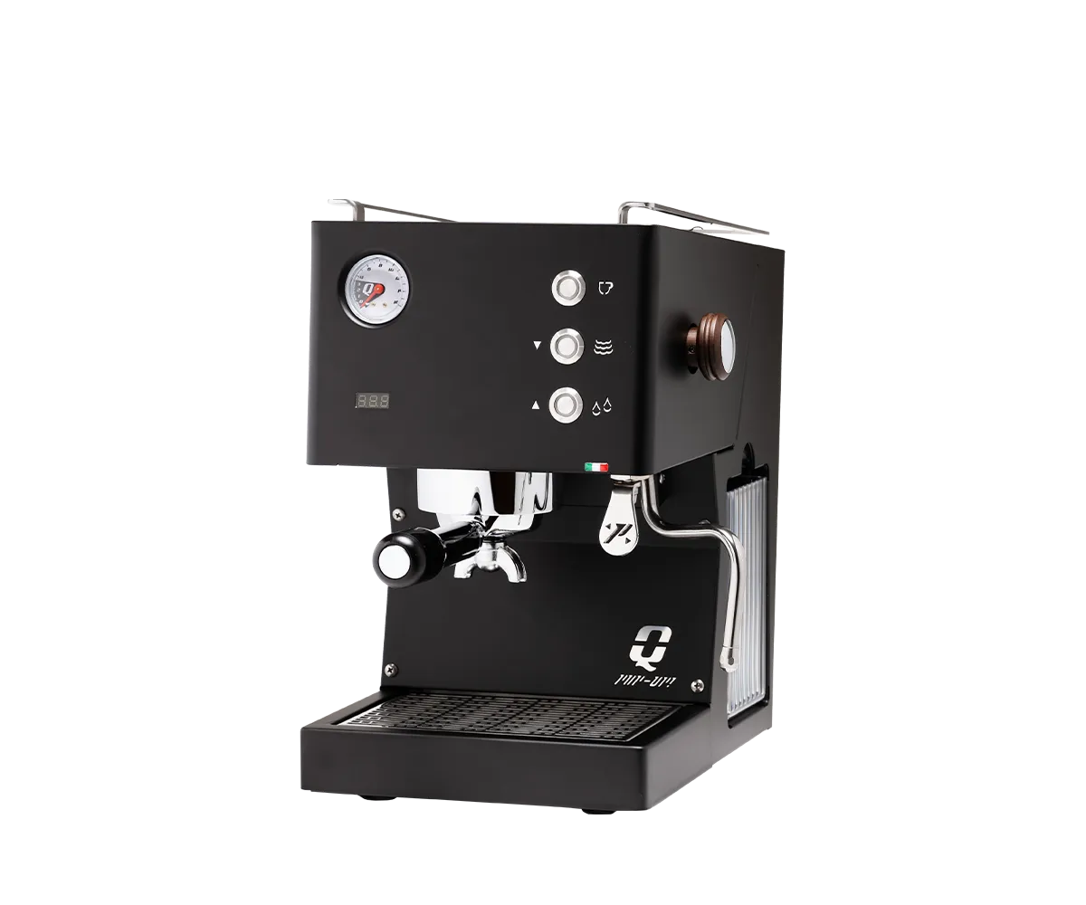
    Quick Mill Pop Up espresso machine in matte black, shown from a front-right angle against a white background. The compact, rectangular machine features a pressure gauge, digital temperature display, three control buttons, chrome portafilter, stainless steel steam wand, cup-warming rails, and removable drip tray.
    Quickmill Pop Up

    We’ve now upgraded again, this time to a Quickmill Pop Up. This fully manual espresso machine is made in Italy. It has a PID temperature controller, an infusion pressure gauge, and a pressure-profiling valve. IT uses a standard 58 mm commercial-sized portafilter, so obtaining a bottomless portafilter should be easy. The learning curve has been steep: first, adjusting the grind size until you could pull a good shot, then playing with the profiling valve to adjust extraction pressure and control the extraction rate. The other tool that has been especially helpful is a subminimal Subscale® Digital Dosing Cup. This device has a built-in scale that weighs in grams or ounces. You can weigh your dose of beans into the grinder, then weigh the shot size, allowing you to pull a shot that weighs about twice the dose. The electronics are IPX-4 protected, so cleanup is as easy as rinsing it out and wiping it with a dry cloth. The Subscale has really helped me refine my process.

    Lavazza Crema e Aroma whole coffee beans in a 1 kg brown and copper-coloured bag. The packaging features the white Lavazza logo, a stylized swirl of coffee above a white espresso cup, and an intensity rating of 8/10.

    Right now, we’re brewing Lavazza Crema e Aroma. It’s an Arabica–Robusta blend, known for its rich body, thick crema, and chocolatey notes. Lavazza’s 8/10 rating reflects the coffee’s intensity, not its quality, caffeine content, or roast level.

    Intensity describes how strong and assertive a coffee tastes. It’s influenced by several characteristics:

    • Roast level: Darker roasting generally produces more pronounced roasted flavours.
    • Body: How rich, full, and substantial the coffee feels in your mouth.
    • Flavour profile: The prominence of bitter, toasted, chocolatey, and other bold notes.
    • Bean blend: Robusta generally contributes more body, bitterness, and crema than Arabica.

    For Crema e Aroma, an intensity of 8/10 means you can expect a fairly bold, full-bodied coffee with a pronounced flavour that stands up well to milk.

    Importantly, 8/10 doesn’t mean high caffeine content. A darker-roasted coffee isn’t necessarily higher in caffeine, although the Robusta component of Crema e Aroma can contribute more caffeine than a pure Arabica blend.

    Lavazza’s specifications confirm that Crema e Aroma is a medium roast with chocolate aromatic notes and an Arabica–Robusta blend, despite its relatively high intensity rating.

    I’ve found flavours in these beans I didn’t know existed. It’s been a real pleasure, and that’s saying something, considering I liked these beans before we got the Pop Up!

    Black Airscape Kilo coffee canister by Planetary Design, featuring a cylindrical metal body with a large handle on top. A transparent lid with a black sealing rim leans against the left side of the canister, while a pile of roasted coffee beans sits in front on the right. The Airscape logo appears near the bottom of the canister against a white background.
    Airscape® Kilo Coffee Canister

    Another thing I’ve found is that filling the Smart Grinder’s 1 kg hopper with beans results in a poor cup. The beans go stale over the week it takes to use them, so I now measure them with the Subscale for every cup. I was given an Airscape® Kilo Coffee Canister.

    One problem with storing coffee beans is that an airtight container isn’t necessarily air-free. Most conventional containers simply seal whatever air is inside along with the beans. That’s not ideal when you’re trying to keep freshly roasted coffee at its best.

    Planetary Design’s Airscape coffee canisters take a different approach. You push down an inner lid until it reaches the top of the beans. As the lid moves down, a one-way valve lets air above the coffee escape. Once you push the lid into position, the valve closes, reducing the oxygen left in the container.

    It’s a simple mechanical arrangement, with no pumps, batteries, or other complications.

    Freshly roasted coffee beans continue to release carbon dioxide (CO₂) for some time after roasting. That’s why you’ll often find one-way degassing valves on specialty coffee bags.

    The Airscape uses a similar principle. Its valve lets gas escape without removing the lid. This is especially useful when storing recently roasted beans.

    Why Does This Matter?

    Coffee contains a variety of aromatic compounds and oils that contribute to its flavour and aroma. Once the beans are roasted, exposure to oxygen gradually changes those compounds through oxidation. Over time, the coffee loses some of the characteristics that made it interesting in the first place.

    Heat, light, and moisture can also contribute to deterioration, so how and where you store your coffee matters.

    An opaque canister protects the beans from light, while Airscape’s sealing system limits exposure to oxygen and moisture. It doesn’t stop the ageing process entirely, of course, but it addresses several of the factors that cause coffee to go stale.

    For me, the appeal is the design’s simplicity. Rather than just sealing the air in with the coffee, the Airscape removes much of it first. It’s an elegant solution to a fairly straightforward problem.

    So that’s where we are now. Making a cup is more complicated now, but the coffee tastes much better!

  • Week 2 of CW Class

    Week 2 of CW Class

    This is post 28 of 28 in the series “Amateur Radio”

    Posts about my adventures in amateur radio.

    1. Step by step – 1st Class
    2. Step-by-Step – 2nd Class
    3. Amateur Radio Codes of Conduct
    4. Step-by-Step – 3rd Class
    5. Step-by-Step – Class 4a
    6. Step-by-Step – Classes 4b & 4c
    7. Step-by-Step—Class 5
    8. Step-by-Step—Class 6
    9. Step-by-Step—Class 7
    10. Step-by-Step—Class 8a
    11. Step-by-Step—Class 8b
    12. Step-by-Step—Class 9
    13. Step-by-Step—Class 10
    14. Step-by-step—Class 11
    15. A Modern Code of Conduct and Ethics for Amateur Radio
    16. Step-by-step—Class 12
    17. Step-by-step—Class 13
    18. Step-by-step—Class 14
    19. Step-by-step—Class 15
    20. Step-by-step—Class 16
    21. Step-by-step—Class 17
    22. Reflection: My Amateur Radio Journey So Far
    23. Authorized to Transmit
    24. Starting the Next Chapter: Advanced & CW
    25. Making Winlink, Pat, ARDOP and a Yaesu FTdx10 Work on an Apple Silicon Mac
    26. Winlink on Apple Silicon: The Files, Scripts and One-Click Launcher
    27. Whispers around the world
    28. Week 2 of CW Class

    You’re probably wondering, “Wait, what happened to Week 1 of CW class?” The short answer: I missed it. So, no post about Week 1. However, I will tell you about Week 2 😀.

    I’m studying CW with Vic DeCicco (VE3YT). Vic teaches the KWARC course. The amazing thing is that KWARC offers the course for free!

    In the first week of the course, Vic taught the first four letters of the Morse alphabet:

    Alpha CharacterMorse
    T—
    E·
    A· —
    N— ·

    The rationale, as I understand it anyway, is that the first two are the simplest code characters to learn, and the second two are combinations of the first two.

    Learning Morse code is neurologically similar in several important respects to learning and decoding a language [1]–[4]. For a young person, this may be easier than for someone in their 60s because the brain’s capacity for rapid neuroplastic change generally declines with age. That does not mean that learning a new language—or learning Morse code—is impossible in your 60s; it may simply require more time and practice.

    There may even be a cognitive side benefit. Studies of bilingualism and later-life cognition suggest that lifelong use of more than one language may contribute to cognitive reserve and has been associated with a later onset of dementia symptoms, although the evidence does not clearly show that bilingualism reduces the overall risk of developing dementia [5]–[7]. So there’s that.

    Ok, so back to learning to “head copy” Morse Code. So far, I’ve found I sometimes have difficulty with the compound codes. It’s first a case of distinguishing the dits from the dahs, and then making the correct association. That’s why I’m practicing as much as I can.

    During the class, Vic briefly reviewed the first four letters, and then introduced a few more:

    Alpha CharacterMorse
    New paragraph (also =) (BT)— · · · —
    Hyphen— · · · · —
    Error· · · · · · · · (8 dits)
    O———
    I· ·
    R· — ·
    S· · ·
    M— —

    After all that, he started sending short sentences constructed with the characters we were learning. I did OK at first, but my ear (more likely my brain) fatigued quickly, leaving me unable to copy most of the sentences. I got occasional letters right, but not enough to form coherent messages.

    I’m using a trainer written by one of the guys in our club, Nick VA3NNW, Nosey Nick’s Nilex Morse Code Trainer.

    The trainer uses the Koch method to teach increasingly difficult codes, using character repetition to help burn the connections between sounds and letters into my brain.

    Since the letter order is the same as the order Vic’s using, that will help with consistency. The more I practice, the more firmly those audible patterns will be etched in, allowing me to hear a string of sounds and hear the words much like hearing them spoken on an SSB phone transmission. That is the essence of headcopying.

    Vic also sent us some practice audio clips that I need to try copying. I’ve got some homework to do!

    Understanding the Koch Method

    The “Koch method” comes from Ludwig Koch’s 1936 doctoral work at the Technische Hochschule Braunschweig, published as Arbeitspsychologische Untersuchung der Tätigkeit bei der Aufnahme von Morsezeichen, zugleich ein neues Anlernverfahren für Funker — roughly, Occupational-psychological investigation of the activity of receiving Morse code, together with a new training method for radio operators. Long Island CW Club

    Koch’s central argument was that Morse should be learned as an auditory Gestalt — a complete sound pattern — rather than as a sequence of dots and dashes. He explicitly compared Morse recognition with other forms of holistic perception, including recognizing melodies and reading words as wholes rather than consciously assembling their constituent parts. Long Island CW Club

    That is the important bit. “Koch training” is not merely “add one letter at a time.”

    What Koch actually proposed

    His procedure essentially reverses the older method.

    Instead of:

    learn all the characters slowly → practise them → gradually increase speed

    Koch proposed:

    begin at a sufficiently high character speed → learn only a couple of characters → progressively add characters while keeping the speed essentially constant.

    He wrote that training could begin with only two characters, practised until the learner could write them down automatically, with additional characters then introduced progressively. Long Island CW Club

    He settled on a target training speed of 60 characters per minute. Koch considered this the optimum introductory speed because below roughly 50 characters/minute the learner could still analyze the individual elements; above that point the character increasingly becomes perceived as a single auditory shape. Long Island CW Club

    In modern amateur-radio terms, 60 characters/minute under the usual PARIS convention is about 12 WPM.

    That is rather interesting because Koch did not argue “the faster the better.” He experimented with 100 characters/minute as an initial speed and found it unnecessarily mentally demanding for ordinary learners as the character set grew. He therefore recommended 60 characters/minute as a practical optimum. Long Island CW Club

    So the authentic Koch principle is closer to:

    Start around 12 WPM, hear each character as a sound object, avoid consciously decoding dits and dahs, and gradually expand your vocabulary of sound patterns.

    Something I hadn’t appreciated until looking at the original

    The modern “Koch method” is actually a simplified descendant of Koch’s method.

    Koch experimented with a two-pitch teaching technique in which dits and dahs were initially presented at slightly different pitches. His idea was to exaggerate the melodic or rhythmic shape of the character and then gradually bring the two pitches together until ordinary single-tone Morse remained. Long Island CW Club

    You virtually never see that in modern Koch trainers.

    He was therefore thinking much more explicitly in terms of auditory pattern formation than most descriptions of his method suggest.

    He summarized his method near the end of the paper this way: the old methods taught all characters slowly and then raised the speed; his method began immediately at 60 characters/minute, initially with two characters, and progressively introduced the rest. Long Island CW Club

    His training results were also respectable.

    PARIS Convention

    The PARIS convention is the standard way to define Morse-code speed in words per minute (WPM).

    The problem is that real words vary wildly in length. So instead of using arbitrary English text, Morse speed is calibrated against the standard word:

    PARIS

    When sent in International Morse with normal spacing, PARIS contains exactly 50 timing units.

    So:

    1 WPM = 50 Morse timing units per minute

    That gives the usual relationship:

    For example, at 20 WPM, one dit lasts:

    A dah is three dits, so 180 ms; the intra-character gap is one dit; the character gap is three dits; and the word gap is seven dits.

    This is why Koch’s 60 characters per minute only approximates 12 WPM.

    Characters per minute and PARIS WPM aren’t exactly interchangeable unless you assume an average character length and spacing.

    For amateur CW today, when someone says 20 WPM, they almost always mean PARIS.

    Koch reported that learners mastered all letters at 60 characters/minute in approximately 24–28 hours of training. Long Island CW Club

    I would treat that figure as a historical experimental result rather than a promise of what every learner should achieve.

    Something I hadn’t appreciated until looking at the original

    The modern “Koch method” is actually a simplified descendant of Koch’s method.

    Koch experimented with a two-pitch teaching technique in which dits and dahs were initially presented at slightly different pitches. His idea was to exaggerate the character’s melodic or rhythmic shape and then gradually bring the two pitches together until ordinary single-tone Morse remained. Long Island CW Club

    You virtually never see that in modern Koch trainers.

    He was therefore thinking much more explicitly in terms of auditory pattern formation than most descriptions of his method suggest.

    He summarized his method near the end of the paper this way: the old methods taught all characters slowly and then raised the speed; his method began immediately at 60 characters/minute, initially with two characters, and progressively introduced the rest. Long Island CW Club

    What about the famous “90% accuracy, then add another character” rule?

    This is where modern lore creeps in.

    The typical present-day description says:

    1. learn two characters;
    2. copy random groups at target speed;
    3. reach about 90% accuracy;
    4. add another character;
    5. repeat.

    That is a perfectly reasonable implementation, but the 90% threshold is not really the essence of Koch’s method, and it does not appear to be the famous explicit rule people sometimes imply it was. Koch talks instead about acquiring sufficient confidence or automaticity before expanding the set. His summary says the characters are added progressively while the receiving speed stays fixed. Long Island CW Club

    So I’d distinguish the Koch principle from modern Koch software conventions.

    Other trainers besides Nosey Nick’s

    One master CW Operator, Ray Burlingame-Goff (G4FON/SK), wrote a CW trainer that you can still download from his website. It’s Windows only, so if you’re a Mac user, you would need to run it in a 32-bit emulation environment unless you’ve got a Windows machine hanging around. G4FON suggests in his 2018 B talk.

    There are many more, of course:

    I’m sure there are many more, and certainly more than I’ve tried.

    Koch versus Farnsworth

    These are often mixed together, but they solve different problems.

    Koch controls vocabulary: only a few characters are initially available, but they are sent at realistic speed.

    Farnsworth controls timing: individual characters are sent rapidly, but extra spacing is inserted between characters and words so the learner has time to recognize them.

    They can be combined — and most modern CW trainers effectively do. You might hear characters at 18–20 WPM while the extra spacing gives an effective text speed of 8–10 WPM, and introduce characters progressively in Koch fashion.

    Koch himself, though, was quite concerned about preserving the correct temporal character shape and avoiding the psychological “changeover” required when someone first learns unnaturally slow Morse and later tries to speed it up. Long Island CW Club

    Morse behaves rather like language acquisition. Koch’s own theoretical explanation is strikingly similar: you want to hear

    -.- → K

    not

    dah + dit + dah → K.

    So… Onward. The class is on Wednesday, and I’m feeling horribly unprepared.

    73 de Doug VE3ZDN


    Refrences

    [1] L. Schlaffke, A. Leemans, L. M. Schweizer, S. Ocklenburg, and T. Schmidt-Wilcke, “Learning Morse Code Alters Microstructural Properties in the Inferior Longitudinal Fasciculus: A DTI Study,” Frontiers in Human Neuroscience, vol. 11, p. 383, Jul. 2017, doi: 10.3389/fnhum.2017.00383. PubMed Central (PMC)

    [2] F. B. Junker, L. Schlaffke, C. Bellebaum, M. Ghio, S. Brühl, N. Axmacher, and T. Schmidt-Wilcke, “Transition From Sublexical to Lexico-Semantic Stimulus Processing,” Frontiers in Systems Neuroscience, vol. 14, 2020, doi: 10.3389/fnsys.2020.522384. PubMed

    [3] F. B. Junker, T. Schmidt-Wilcke, A. Schnitzler, and J. Lange, “Temporal dynamics of oscillatory activity during nonlexical language decoding: Evidence from Morse code and magnetoencephalography,” Human Brain Mapping, vol. 44, no. 17, pp. 6185–6197, 2023, doi: 10.1002/hbm.26505.

    [4] F. B. Junker, L. Schlaffke, J. Lange, and T. Schmidt-Wilcke, “The angular gyrus serves as an interface between the non-lexical reading network and the semantic system: evidence from dynamic causal modeling,” Brain Struct Funct, vol. 229, no. 3, pp. 561–575, Mar. 2023, doi: 10.1007/s00429-023-02624-z.

    [5] E. Bialystok, F. I. M. Craik, and M. Freedman, “Bilingualism as a protection against the onset of symptoms of dementia,” Neuropsychologia, vol. 45, no. 2, pp. 459–464, 2007, doi: 10.1016/j.neuropsychologia.2006.10.009. PubMed

    [6] S. Alladi, T. H. Bak, V. Duggirala, B. Surampudi, M. Shailaja, A. K. Shukla, J. R. Chaudhuri, and S. Kaul, “Bilingualism delays age at onset of dementia, independent of education and immigration status,” Neurology, vol. 81, no. 22, pp. 1938–1944, 2013, doi: 10.1212/01.wnl.0000436620.33155.a4. PubMed

    [7] N. Mukadam, A. Sommerlad, and G. Livingston, “The relationship of bilingualism compared to monolingualism to the risk of cognitive decline or dementia: A systematic review and meta-analysis,” Journal of Alzheimer’s Disease, vol. 58, no. 1, pp. 45–54, 2017, doi: 10.3233/JAD-170131.

    [8] D. M. Clawson, A. F. Healy, K. A. Ericsson, and L. E. Bourne, “Retention and transfer of morse code reception skill by novices: Part-whole training.,” Journal of Experimental Psychology: Applied, vol. 7, no. 2, pp. 129–142, 2001, doi: 10.1037/1076-898X.7.2.129.

    [9] F. S. Keller, “SECTION OF PSYCHOLOGY : STIMULUS DISCRIMINATION AND MORSE CODE LEARNING*,” Trans NY Acad Sci, vol. 15, no. 6 Series II, pp. 195–203, Apr. 1953, doi: 10.1111/j.2164-0947.1953.tb00351.x.

  • Whispers around the world

    Whispers around the world

    This is post 27 of 28 in the series “Amateur Radio”

    Posts about my adventures in amateur radio.

    1. Step by step – 1st Class
    2. Step-by-Step – 2nd Class
    3. Amateur Radio Codes of Conduct
    4. Step-by-Step – 3rd Class
    5. Step-by-Step – Class 4a
    6. Step-by-Step – Classes 4b & 4c
    7. Step-by-Step—Class 5
    8. Step-by-Step—Class 6
    9. Step-by-Step—Class 7
    10. Step-by-Step—Class 8a
    11. Step-by-Step—Class 8b
    12. Step-by-Step—Class 9
    13. Step-by-Step—Class 10
    14. Step-by-step—Class 11
    15. A Modern Code of Conduct and Ethics for Amateur Radio
    16. Step-by-step—Class 12
    17. Step-by-step—Class 13
    18. Step-by-step—Class 14
    19. Step-by-step—Class 15
    20. Step-by-step—Class 16
    21. Step-by-step—Class 17
    22. Reflection: My Amateur Radio Journey So Far
    23. Authorized to Transmit
    24. Starting the Next Chapter: Advanced & CW
    25. Making Winlink, Pat, ARDOP and a Yaesu FTdx10 Work on an Apple Silicon Mac
    26. Winlink on Apple Silicon: The Files, Scripts and One-Click Launcher
    27. Whispers around the world
    28. Week 2 of CW Class

    I haven’t been an amateur radio operator for a long time, but I’ve already discovered that one of the pleasures of the hobby is that there is always some new rabbit hole available when you feel like falling into one.

    My latest rabbit hole has been digital radio.

    It started innocently enough. I wanted to experiment with some weak-signal digital modes, learn a bit more about HF propagation, and get the Yaesu FTdx10 talking properly to the various bits of software on my M1 MacBook Air.

    A few weeks later I was watching five watts of RF from a dipole hanging in a maple tree being reported from Australia, installing propagation-prediction software descended from programs written when computers ate punch cards, talking to stations using text modes at signals buried in the noise, and developing opinions about USB audio levels that no reasonable person should possess.

    So, yes. That escalated quickly.

    First, make the computer talk to the radio

    My station is fairly modest.

    The radio is a Yaesu FTdx10. My main computer is an M1 MacBook Air named Timnit. For antennas, I have been using resonant wire dipoles rather than anything exotic.

    That sounds simple.

    It isn’t.

    Modern digital amateur radio has several separate things that all need to work at once. The computer has to control the radio frequency and mode. Something has to key the transmitter. Audio has to get from the computer to the radio at the correct level. Received audio has to travel in the other direction. And, ideally, two different programs shouldn’t simultaneously decide that they own the CAT interface.

    My setup gradually evolved around FLrig as the intermediary between the radio and applications such as fldigi. WSJT-X handles modes such as FT8 and WSPR, while JS8Call handles JS8. I have also experimented with fldigi modes including Olivia, and eventually wandered into Winlink, ARDOP and VARA HF.

    There was quite a lot of:

    “Why isn’t this transmitting?”

    followed by:

    “Oh.”

    One particularly fine episode involved troubleshooting what seemed like a complete absence of RF from ARDOP, only to discover that the external RF monitor I was using to check for RF was switched off.

    DOH.

    Once you sort that out, though, digital radio becomes enormously interesting.

    WSPR: the gateway drug

    WSPR stands for Weak Signal Propagation Reporter.

    It isn’t really a conversational mode. A WSPR transmission contains little more than a callsign, grid square and transmitter power. The transmission takes nearly two minutes and occupies only a few hertz of bandwidth.

    The clever bit is that receivers running WSPR software all over the world decode these tiny signals and upload their reports to a central database.

    You transmit.

    Then you look at a map.

    And that is where the trouble begins.

    My first serious experiments were on 20 metres, transmitting only 5 W into a dipole.

    The antenna wasn’t on a tower. It wasn’t even particularly high.

    It was suspended from the maple tree in our backyard, roughly in an inverted-V arrangement, with the apex about five metres above ground and the ends perhaps two metres up.

    And people started hearing me.

    First around North America.

    Then Europe.

    Then farther.

    Germany.

    Austria.

    The Canary Islands.

    South Africa.

    Australia.

    At one point, VK5ARG in South Australia reported my five-watt WSPR transmission from approximately 16,500 km away.

    Another Australian station, VK5EI, was a little farther still.

    Let that sink in for a moment.

    Five watts.

    A piece of wire hanging from a tree in Kitchener.

    Australia.

    That works out to roughly 3,300 km per watt, although of course kilometres-per-watt isn’t actually how propagation works. It is nevertheless a deeply satisfying number.

    On another evening, VK5ARG was hearing me at around -6 or -7 dB signal-to-noise ratio.

    At that point the appropriate technical diagnosis was essentially:

    “Yeah. The radio is working.”

    Watching the ionosphere move

    What made WSPR really fascinating wasn’t simply collecting distant spots.

    It was watching them change.

    On a good evening, I could watch my signal being reported simultaneously across North America, Europe, South America and Australia. Then, perhaps half an hour later, the Australians would disappear. Europe would begin to fade. Strong reports would remain from Texas, Florida or the western United States.

    The RF map was rearranging itself in front of me.

    That was when propagation stopped being an abstract collection of terms such as MUF, F2 layer, grey line and skip distance.

    You can read about those things.

    It is quite another experience to watch them happen.

    WSPR also taught me very quickly that a band isn’t simply “open” or “closed.”

    Open to where?

    For whom?

    At what angle?

    In which direction?

    A path can disappear in one direction while remaining excellent in another. A receiver might hear very little, while stations thousands of kilometres away still hear your transmitter perfectly well.

    The ionosphere apparently has no interest in making things tidy for beginners.

    Then I borrowed a 17-metre dipole

    Naturally, having established that the 20-metre antenna worked, the obvious response was to hang another wire in the tree.

    I borrowed and lofted a 17-metre dipole and put 5 W of WSPR into it on 18.1061 MHz.

    On the first serious run, the signal reached Europe, North America, the Canary Islands…

    …and Australia.

    VK5ARG again.

    About 16,519 km away at -20 dB.

    That answered the question of whether the 17-metre dipole worked.

    The more interesting thing was what happened afterwards. That extraordinary long-path opening disappeared fairly quickly, while reports across North America and the Atlantic remained strong.

    For a brief period, apparently, the propagation geometry had aligned just right.

    WSPR caught it.

    Without WSPR, I would probably never have known it existed.

    FT8: signals you can barely hear, everywhere

    FT8 is related to WSPR in spirit but designed for making contacts rather than simply reporting propagation.

    On 20 metres, FT8 activity centres around 14.074 MHz.

    The exchanges are highly structured and very short: callsigns, grid squares, signal reports and acknowledgements. It isn’t exactly sparkling conversation.

    But that isn’t really the point.

    FT8 is astonishing at recovering signals well below the noise floor.

    Watching the WSJT-X decode window fill with stations that I could barely — or couldn’t — hear by ear was another one of those small amateur-radio revelations.

    Oddly, WSPR also gave me a useful lesson about interpreting FT8 activity. There were occasions when WSPR showed that my signal was travelling extremely well while the FT8 receive window looked rather sparse.

    That didn’t mean the antenna had suddenly failed.

    Different modes have different sensitivities, different activity levels and different operating patterns. Propagation can also be asymmetric.

    The absence of FT8 decodes doesn’t necessarily mean the absence of propagation.

    WSPR had given me another instrument for understanding what I was seeing.

    JS8: FT8 discovers conversation

    Then there is JS8.

    JS8 uses a modulation technique derived from FT8, but instead of exchanging a rigid sequence of signal reports, JS8Call allows actual text communication.

    That immediately appealed to me.

    On 20 metres, JS8 activity is normally found around 14.078 MHz. Once I had JS8Call, FLrig and the FTdx10 behaving themselves, I began decoding stations.

    Then I transmitted my own CQ.

    Then somebody answered.

    My early contacts included KK4QIG in Florida and AF4SH in Georgia.

    They weren’t spectacular DX by WSPR standards, but they felt completely different.

    There is something strangely satisfying about exchanging actual typed messages with another station using signals that may be hovering around the noise floor.

    My early operating technique was not exactly flawless.

    I discovered that repeatedly sending CQ and heartbeat messages is considered somewhat enthusiastic.

    At various moments, I typed other people’s callsigns where my own should have gone.

    I once mixed a traditional “599” report into a mode whose software was already telling me the actual signal-to-noise ratio.

    In other words, I behaved exactly like someone learning a new mode.

    But the contacts worked.

    And each one made the underlying machinery slightly less mysterious.

    Olivia and the wonderfully crowded world of fldigi

    At some point I opened fldigi’s mode menu.

    This was a tactical error.

    There are approximately six billion digital modes in there.

    PSK.

    RTTY.

    Olivia.

    Contestia.

    Thor.

    DominoEX.

    FSQ.

    Modes apparently invented by people who believed amateur radio really needed another modulation scheme.

    Obviously, I wanted to try them all.

    Olivia particularly interested me because it is designed for reliable keyboard-to-keyboard communication under poor signal conditions.

    Getting the transmit audio adjusted properly became another lesson in modern radio technique. The goal is not to hammer the radio until the ALC meter lights up like Christmas.

    Quite the opposite.

    With the FTdx10 in DATA-U mode, I eventually found settings that produced clean RF with essentially no ALC indication. The computer provides enough audio to drive the transmitter properly, and no more.

    Once you begin looking at digital signals that way, “more” stops automatically meaning “better.”

    Down another rabbit hole: Winlink

    The next project was Winlink.

    Winlink is a worldwide radio email system used extensively in emergency communications. Messages can travel through HF gateways even when conventional Internet infrastructure isn’t available.

    I wanted to make it work from the Mac.

    This involved MacWinlink, various helper applications, ARDOP, VARA HF running under Wine, CAT control, USB audio routing and an impressive collection of opportunities for one software component to misunderstand another.

    Eventually, though, I connected through an HF RMS gateway in Georgia using VARA HF.

    That was another satisfying little milestone.

    The important part wasn’t sending email by radio.

    Amateur radio has been doing that sort of thing for decades.

    The satisfying part was understanding enough of the entire chain — computer, modem, audio, CAT, radio, propagation and remote station — to know why it worked.

    And, increasingly, why it sometimes didn’t.

    Propagation prediction meets propagation reality

    Once I had accumulated enough WSPR observations, another question appeared:

    Could I predict this?

    That led me to VOACAP.

    VOACAP is a descendant of ionospheric propagation models developed for professional HF communications. It can estimate the probability of communication between two locations by frequency and time of day.

    Naturally, I installed the command-line version.

    Naturally, it initially complained about file paths.

    Naturally, some of its conventions seem designed for when computer operators carried boxes of punch cards.

    Eventually I had it running.

    One path I examined was from my station, VE3ZDN in grid EN93tj, to DK6UG in Germany, roughly 6,400 km away.

    The predictions suggested that 17 metres should perform particularly well earlier in the evening, with 20 metres becoming the more reliable path later.

    Then I could compare that prediction with actual WSPR reports.

    This is where the whole experiment became much more than simply chasing DX.

    I was doing a tiny version of radio science.

    Make a prediction.

    Transmit.

    Collect observations.

    Compare the result.

    Change something.

    Try again.

    Five watts changes your sense of scale

    Perhaps the biggest surprise from all this has been how little RF power is required when everything else cooperates.

    Five watts is about what a USB charger might deliver.

    Yet five watts of RF, applied to a resonant dipole and launched into the ionosphere at the right moment, can cross an ocean.

    Several oceans, apparently.

    That doesn’t mean power is irrelevant. More power gives additional link margin, and there are plenty of circumstances where it matters.

    But weak-signal digital modes make something visible that ordinary voice operating can conceal:

    The path itself is doing most of the work.

    The antenna matters.

    The noise floor matters.

    Timing matters.

    The ionosphere matters enormously.

    And clever signal processing can extract astonishing amounts of information from almost nothing.

    The real appeal

    I think there’s a tendency to divide amateur radio into “traditional” and “computer” radio. I don’t find the distinction very useful.

    When my five-watt WSPR transmission is decoded in Australia, I am still doing what radio amateurs have always done: putting RF into an antenna and wondering who can hear it.

    The computer simply lets me see the answer.

    FT8 shows me signals I would otherwise miss.

    JS8 lets me turn those weak signals into a conversation.

    WSPR turns thousands of receiving stations into a gigantic propagation experiment.

    VOACAP lets me test theory against observation.

    Winlink adds practical communications capability.

    And somewhere underneath all the software, USB cables and TCP ports is still the same wonderfully improbable phenomenon that has fascinated radio operators for more than a century:

    I put a small alternating current into a wire in my backyard.

    A fraction of a second later, some of that energy is on the other side of the planet.

    Then somebody’s computer says:

    “I heard you.”

    That still seems like magic.

    I hope it always does.

    And, of course, I have barely scratched the surface.

    There are still all those other modes in the fldigi menu.

    This may have been a mistake.

  • Winlink on Apple Silicon: The Files, Scripts and One-Click Launcher

    Winlink on Apple Silicon: The Files, Scripts and One-Click Launcher

    This is post 26 of 28 in the series “Amateur Radio”

    Posts about my adventures in amateur radio.

    1. Step by step – 1st Class
    2. Step-by-Step – 2nd Class
    3. Amateur Radio Codes of Conduct
    4. Step-by-Step – 3rd Class
    5. Step-by-Step – Class 4a
    6. Step-by-Step – Classes 4b & 4c
    7. Step-by-Step—Class 5
    8. Step-by-Step—Class 6
    9. Step-by-Step—Class 7
    10. Step-by-Step—Class 8a
    11. Step-by-Step—Class 8b
    12. Step-by-Step—Class 9
    13. Step-by-Step—Class 10
    14. Step-by-step—Class 11
    15. A Modern Code of Conduct and Ethics for Amateur Radio
    16. Step-by-step—Class 12
    17. Step-by-step—Class 13
    18. Step-by-step—Class 14
    19. Step-by-step—Class 15
    20. Step-by-step—Class 16
    21. Step-by-step—Class 17
    22. Reflection: My Amateur Radio Journey So Far
    23. Authorized to Transmit
    24. Starting the Next Chapter: Advanced & CW
    25. Making Winlink, Pat, ARDOP and a Yaesu FTdx10 Work on an Apple Silicon Mac
    26. Winlink on Apple Silicon: The Files, Scripts and One-Click Launcher
    27. Whispers around the world
    28. Week 2 of CW Class

    In my previous post, I told the story of getting Winlink, Pat, ARDOP and my Yaesu FTDX10 working reliably on an Apple Silicon Mac.

    That post was about the journey: the false starts, the serial-port detective work, the PTT problem, the ARDOP audio problem, the first successful RMS connection, and the eventual realization that the cleanest architecture was much simpler than the one I started with.

    This post is the practical companion.

    If you want to build something similar, this is where I’m putting the pieces together in one place: the launcher, the shell scripts, the Core Location/GPS bridge, and the configuration details that made the whole thing work.

    A quick warning before we start: do not blindly copy my device names and assume they will match yours. The FTdx10 serial ports on your Mac will almost certainly have different names. Treat the files here as a working template, not a universal drop-in installer.

    What this setup does

    My finished launcher brings up the entire Winlink station in one go.

    The architecture looks like this:

    macOS Core Location
            ↓
    CoreLocationCLI
            ↓
    NMEA generator
            ↓
    socat pseudo-terminal
            ↓
    gpsd
            ↓
    Pat
            │
            ├── rigctld ── CAT ── FTDX10 Enhanced COM
            │
            └── ardopcf ── RTS ── FTDX10 Standard COM
                           │
                           └── USB AUDIO CODEC

    The FTdx10’s USB interface exposes two virtual COM ports, and that is what makes this arrangement so clean. Yaesu assigns the Enhanced COM Port to CAT communications and the Standard COM Port to transmit control, such as PTT and digital operation.

    In my installation:

    /dev/cu.usbserial-00F490390

    is the Enhanced CAT port, while:

    /dev/cu.usbserial-00F490391

    is the Standard TX-control port.

    Your names will be different.

    Required software

    The setup assumes the following are installed:

    Pat
    Hamlib
    ardopcf
    CoreLocationCLI
    gpsd
    socat

    On my machine, Homebrew handles most of the supporting utilities:

    brew install hamlib
    brew install corelocationcli
    brew install gpsd
    brew install socat

    Pat and ardopcf need to be installed separately according to their respective project instructions.

    You can confirm that Hamlib recognizes the FTdx10 with:

    rigctl -l | grep -i FTDX10

    My installation reports:

    1042  Yaesu  FTDX-10  Stable

    Finding your FTdx10 serial ports

    Start with:

    ls /dev/cu.* /dev/tty.* | grep -Ei 'usb|serial'

    You should see two serial devices associated with the FTdx10.

    To identify the Enhanced CAT port, test each candidate with:

    rigctl \
      -m 1042 \
      -r /dev/cu.YOURPORT \
      -s 38400

    At the Rig command: prompt, enter:

    f

    If Hamlib returns the radio’s current frequency, you have found the CAT port.

    On my Mac, that test returned:

    Frequency: 14009914

    which matched the frequency displayed on the radio and confirmed that /dev/cu.usbserial-00F490390 was the correct CAT device.

    The remaining FTdx10 USB serial device is then the Standard TX‑control port.

    The radio setting that matters

    On the FTdx10, PTT must be configured so that the USB virtual COM port can control transmit.

    The relevant setting is:

    RPTT SELECT

    and for my installation it is set to:

    RTS

    Yaesu documents RTS/DTR as the USB virtual-COM transmit-control option for digital operation.

    Pat configuration

    Pat uses rigctld for tuning and ardopcf for the modem.

    The important Hamlib section of my Pat configuration is:

    "hamlib_rigs": {
      "FTdx10": {
        "network": "tcp",
        "address": "127.0.0.1:4532",
        "VFO": ""
      }
    }

    The ARDOP section is:

    "ardop": {
      "addr": "127.0.0.1:8515",
      "arq_bandwidth": {
        "Forced": false,
        "Max": 2000
      },
      "connect_requests": 10,
      "rig": "FTdx10",
      "ptt_ctrl": false,
      "beacon_interval": 0,
      "cwid_enabled": true
    }

    The important detail is:

    "ptt_ctrl": false

    Pat is not responsible for PTT in this setup.

    ardopcf owns the Standard USB serial port and uses RTS directly.

    That division of labour is what finally made the setup reliable.

    Starting rigctld

    The working Hamlib command is:

    rigctld \
      -m 1042 \
      -r /dev/cu.usbserial-00F490390 \
      -s 38400 \
      -T 127.0.0.1 \
      -t 4532

    That gives Pat a network-accessible CAT interface at:

    127.0.0.1:4532

    Starting ARDOP

    This is the working ardopcf command on my station:

    build/macos/ardopcf \
      -p /dev/cu.usbserial-00F490391 \
      --hostcommands "MYCALL VE3ZDN;DRIVELEVEL 2" \
      8515 \
      "USB AUDIO  CODEC" \
      "USB AUDIO  CODEC"

    A few notes are worth calling out.

    First, -p assigns the Standard serial port to PTT using RTS.

    Second, I explicitly set:

    MYCALL VE3ZDN

    and:

    DRIVELEVEL 2

    at startup.

    Third, the FTdx10 USB audio device on my Mac appears as:

    USB AUDIO  CODEC

    with two spaces between AUDIO and CODEC.

    That detail caused more head-scratching than it deserved.

    Your audio device name may differ.

    The Core Location to GPSd bridge

    Pat can use GPSd to update its locator automatically.

    The Mac does not expose Core Location as a conventional serial GPS receiver, so I added a small bridge.

    The flow is:

    CoreLocationCLI
          ↓
    Python NMEA generator
          ↓
    socat PTY pair
          ↓
    gpsd
          ↓
    Pat

    The Python script is called:

    ~/bin/corelocation-nmea

    and looks like this:

    #!/usr/bin/env python3
    
    import json
    import subprocess
    import time
    import datetime
    import sys
    
    
    def checksum(sentence):
        c = 0
        for ch in sentence:
            c ^= ord(ch)
        return f"{c:02X}"
    
    
    def dd_to_nmea(value, is_lat):
        value = float(value)
    
        hemi = (
            ("N" if value >= 0 else "S")
            if is_lat
            else ("E" if value >= 0 else "W")
        )
    
        value = abs(value)
    
        deg = int(value)
        minutes = (value - deg) * 60
    
        if is_lat:
            field = f"{deg:02d}{minutes:07.4f}"
        else:
            field = f"{deg:03d}{minutes:07.4f}"
    
        return field, hemi
    
    
    def emit(sentence):
        full = f"${sentence}*{checksum(sentence)}"
        print(full, flush=True)
    
    
    while True:
        try:
            result = subprocess.run(
                ["CoreLocationCLI", "--json"],
                capture_output=True,
                text=True,
                check=True,
                timeout=10
            )
    
            data = json.loads(result.stdout)
    
            lat, ns = dd_to_nmea(data["latitude"], True)
            lon, ew = dd_to_nmea(data["longitude"], False)
    
            now = datetime.datetime.now(datetime.timezone.utc)
    
            hhmmss = now.strftime("%H%M%S")
            ddmmyy = now.strftime("%d%m%y")
    
            rmc = (
                f"GPRMC,{hhmmss}.00,A,"
                f"{lat},{ns},{lon},{ew},"
                f"0.0,0.0,{ddmmyy},,,A"
            )
    
            emit(rmc)
    
            gga = (
                f"GPGGA,{hhmmss}.00,"
                f"{lat},{ns},{lon},{ew},"
                f"1,08,1.0,0.0,M,0.0,M,,"
            )
    
            emit(gga)
    
        except Exception as e:
            print(
                f"# CoreLocation error: {e}",
                file=sys.stderr,
                flush=True
            )
    
        time.sleep(2)

    I create the pseudo-terminal pair with socat, feed the NMEA output into one side, and give the other side to real gpsd.

    Pat is configured with:

    "gpsd": {
      "enable_http": false,
      "allow_forms": false,
      "use_server_time": false,
      "update_locator": true,
      "addr": "127.0.0.1:2947"
    }

    When everything is working, Pat logs something like:

    Locator changed from EN93tj to EN93TJ

    which confirms that it has accepted the live position from GPSd.

    The one-click launcher

    I wrapped everything in a small AppleScript application called:

    Winlink ARDOP.app

    The AppleScript itself is intentionally simple:

    set choice to button returned of (display dialog ¬
        "Winlink ARDOP station control" buttons {"Cancel", "Stop", "Start"} ¬
        default button "Start" with title "Winlink ARDOP")
    
    if choice is "Start" then
    
        display notification "Starting Winlink ARDOP station…" ¬
            with title "Winlink ARDOP"
    
        do shell script "/bin/zsh -lc '$HOME/bin/start-winlink-ardop' 2>&1"
    
        display dialog "Winlink ARDOP startup completed." ¬
            buttons {"OK"} default button "OK" ¬
            with title "Winlink ARDOP"
    
    else if choice is "Stop" then
    
        display notification "Stopping Winlink ARDOP station…" ¬
            with title "Winlink ARDOP"
    
        do shell script "/bin/zsh -lc '$HOME/bin/stop-winlink-ardop' 2>&1"
    
        display dialog "Winlink ARDOP station shut down." ¬
            buttons {"OK"} default button "OK" ¬
            with title "Winlink ARDOP"
    
    end if

    The application is really just a friendly wrapper around:

    ~/bin/start-winlink-ardop

    and:

    ~/bin/stop-winlink-ardop

    That means the logic stays in ordinary shell scripts where it is easy to inspect and troubleshoot.

    What the startup script does

    The startup script:

    • verifies the required programs are installed;
    • verifies both FTDX10 serial devices exist;
    • creates the GPS pseudo-terminal pair;
    • starts the Core Location NMEA generator;
    • starts GPSd;
    • starts rigctld;
    • checks that CAT can actually read the FTDX10 frequency;
    • starts ardopcf;
    • opens both USB audio channels;
    • enables RTS PTT;
    • sets my callsign and TX drive level;
    • starts Pat;
    • waits for the required TCP ports to come up;
    • opens the ARDOP and Pat browser interfaces;
    • writes logs for troubleshooting.

    The shutdown script stops everything in reverse order and cleans up the GPS pseudo-terminal links.

    That last point is important.

    During development, I discovered that stale Pat or ARDOP processes could leave things in a strange state. A clean shutdown and restart usually restored normal operation immediately.

    For that reason, I prefer the launcher to own the whole stack rather than casually reusing old processes.

    Logging

    The launcher writes its logs to:

    ~/winlink-launcher-logs

    including:

    pat.log
    ardopcf.log
    rigctld.log
    gpsd.log
    corelocation-nmea.log
    socat-gps.log

    These logs are extremely useful.

    For example, this:

    Mod4FSKDataAndPlay() called when not TXEnabled. Ignoring.

    tells a very different story from:

    Sending Frame Type ConReq2000M

    and once you start seeing things such as:

    DataACK
    BREAK
    4FSK...

    you are looking at real two-way ARDOP traffic.

    Download files

    I’m making the following files available with this post:

    start-winlink-ardop
    stop-winlink-ardop
    corelocation-nmea
    Winlink ARDOP AppleScript source
    sample Pat configuration

    I recommend reading through every script before running it.

    At minimum, you will need to change:

    callsign
    CAT serial device
    PTT serial device
    audio device name

    and possibly:

    CAT baud rate
    ARDOP drive level
    paths to Pat and ardopcf

    depending on your installation.

    A few final cautions

    This setup works on my FTdx10 and my Apple Silicon Mac.

    It is not a turnkey universal installer.

    In particular, do not assume my:

    DRIVELEVEL 2

    is correct for your radio.

    Set transmit audio conservatively and verify that you are not overdriving the transmitter.

    Also remember that successful software configuration does not guarantee a successful RMS connection.

    My first confirmed connection was to K5RAV, about 2,500 km away.

    A later successful connection was to N0DAJ, about 3,000 km away.

    Several much closer stations failed simply because 20-metre propagation favoured the longer paths at the time.

    Once you know the radio is really transmitting valid ARDOP frames, start considering propagation before tearing your software apart again.

    That lesson would have saved me several hours.

    Final result

    At this point, I can click one icon, press Start, and end up with:

    live Mac location
    GPSd
    Pat
    rigctld
    ARDOP
    FTDX10 CAT control
    FTDX10 RTS PTT
    USB modem audio

    all running together.

    And most importantly, I’ve connected successfully to multiple Winlink RMS stations over HF.

    If this collection of scripts saves another Mac user even half the time I spent figuring it out, publishing them will have been worthwhile.

    73,

    Doug Nix, VE3ZDN
    Kitchener, Ontario
    EN93tj

  • Making Winlink, Pat, ARDOP and a Yaesu FTdx10 Work on an Apple Silicon Mac

    Making Winlink, Pat, ARDOP and a Yaesu FTdx10 Work on an Apple Silicon Mac

    This is post 25 of 28 in the series “Amateur Radio”

    Posts about my adventures in amateur radio.

    1. Step by step – 1st Class
    2. Step-by-Step – 2nd Class
    3. Amateur Radio Codes of Conduct
    4. Step-by-Step – 3rd Class
    5. Step-by-Step – Class 4a
    6. Step-by-Step – Classes 4b & 4c
    7. Step-by-Step—Class 5
    8. Step-by-Step—Class 6
    9. Step-by-Step—Class 7
    10. Step-by-Step—Class 8a
    11. Step-by-Step—Class 8b
    12. Step-by-Step—Class 9
    13. Step-by-Step—Class 10
    14. Step-by-step—Class 11
    15. A Modern Code of Conduct and Ethics for Amateur Radio
    16. Step-by-step—Class 12
    17. Step-by-step—Class 13
    18. Step-by-step—Class 14
    19. Step-by-step—Class 15
    20. Step-by-step—Class 16
    21. Step-by-step—Class 17
    22. Reflection: My Amateur Radio Journey So Far
    23. Authorized to Transmit
    24. Starting the Next Chapter: Advanced & CW
    25. Making Winlink, Pat, ARDOP and a Yaesu FTdx10 Work on an Apple Silicon Mac
    26. Winlink on Apple Silicon: The Files, Scripts and One-Click Launcher
    27. Whispers around the world
    28. Week 2 of CW Class

    Or: How I finally sent Winlink mail from my Mac

    Hey, what’s this Winlink thing?

    That innocent question cost me rather more time than I expected.

    I’m an amateur radio operator, VE3ZDN, and one of the things I’ve been gradually assembling is a useful emergency/digital communications toolkit. I already use modes such as WSPR, JS8Call and fldigi, and I wanted to add Winlink to the mix.

    Winlink is essentially a worldwide radio email system. A station can connect over RF to an RMS — a Radio Message Server — and exchange email even when ordinary Internet access isn’t available. That makes it particularly interesting for emergency communications.

    At least, that’s the theory.

    I wanted to do it from my M1 MacBook Air, using my Yaesu FTdx10, preferably without dedicating a Windows computer to the job.

    What followed was several days of serial ports, audio devices, CAT commands, ARDOP frames, propagation experiments, bugs, false starts, and more than one moment when I came perilously close to deciding that Winlink simply wasn’t worth the trouble.

    And then it worked.

    Twice.

    And now I have a one-click Mac launcher that brings up the entire station, controls the FTdx10, starts the ARDOP modem, obtains my current Mac location and feeds it into Pat through GPSd, and opens the interfaces I need.

    This post documents the whole adventure.


    The station

    My relevant hardware and software are:

    • Apple Silicon MacBook Air, which I call Timnit
    • macOS 26.6.2
    • Yaesu FTdx10
    • 20 m inverted-V dipole at 5 m
    • USB connection directly between Mac and radio
    • Pat, the open-source Winlink client
    • ardopcf, the ARDOP modem
    • Hamlib 4.7.2
    • rigctld
    • CoreLocationCLI
    • gpsd
    • socat

    My callsign is VE3ZDN.

    The FTdx10 turns out to be particularly well suited to this because its USB interface actually exposes two virtual serial ports.

    Yaesu describes them this way:

    • Enhanced COM Port: CAT communication — frequency and mode control
    • Standard COM Port: transmit control — PTT, CW keying and digital operation

    That seemingly minor fact turned out to be the key to the whole installation.


    Attempt number one: MacWinlink

    My first instinct was the obvious one: install MacWinlink.

    That led me into Wine, WoW64, helper applications and beta releases. I was working with a beta MacWinlink release and its helper application, and at one point discovered that the Wine prefix was missing its syswow64 environment.

    I filed a bug report with the developer, John, and he was already working on another beta.

    I still hope MacWinlink develops into a great native-feeling solution. But for my purposes — particularly because Winlink is supposed to be part of an emergency communications toolkit — I needed something I could understand and troubleshoot all the way down.

    So I moved sideways.


    Enter Pat

    Pat is an open-source Winlink client written in Go. It runs nicely on macOS and exposes a browser-based interface.

    That immediately appealed to me.

    The basic idea is straightforward:

    Pat
     ↓
    ARDOP modem
     ↓
    radio
     ↓
    RMS Winlink station

    Except that the computer also needs to:

    1. tune the radio to the RMS frequency;
    2. key the transmitter;
    3. send and receive modem audio.

    Those are three distinct jobs.

    My initial configuration used flrig as part of the CAT-control chain. It worked something like:

    Pat
     ↓
    rigctld
     ↓
    flrig
     ↓
    FTDX10

    Meanwhile, ardopcf handled the modem audio.

    This nearly worked.

    And “nearly works” is one of the more dangerous phrases in technical troubleshooting.


    The first big breakthrough: flrig wasn’t necessary

    I eventually came across Carl Howe, WG1V’s excellent post about running Winlink and Pat on an M1 Mac.

    Something in it made me stop.

    Why was I using flrig at all?

    Hamlib’s rigctld can talk directly to a supported transceiver. My installed Hamlib version confirmed that the FTDX10 has a stable backend:

    1042  Yaesu  FTDX-10  Stable

    My Mac exposed two serial devices:

    /dev/cu.usbserial-00F490390
    /dev/cu.usbserial-00F490391

    So I tried this:

    rigctl -m 1042 \
      -r /dev/cu.usbserial-00F490390 \
      -s 38400

    At the Rig command: prompt, I entered:

    f

    The answer:

    Frequency: 14009914

    Bingo.

    Hamlib was talking directly to the FTDX10. The test and the Hamlib model identification are captured in my troubleshooting log.

    No flrig.

    Next I started rigctld:

    rigctld \
      -m 1042 \
      -r /dev/cu.usbserial-00F490390 \
      -s 38400 \
      -T 127.0.0.1 \
      -t 4532

    Hamlib opened the FTdx10 successfully on model 1042 and the serial device above.

    Pat could now talk to:

    127.0.0.1:4532

    and tune the radio directly.

    That eliminated an entire layer of software.

    The new architecture was:

    Pat
     ↓
    rigctld
     ↓
    FTDX10

    Much better.


    But it still wouldn’t transmit

    Pat would tune the Yaesu correctly.

    I would select an RMS station and see:

    QSY ardop: 14102.3
    Connecting to WG0A-10 (ardop)...
    Unable to establish connection to remote: Connect timeout

    But the FTdx10 never went into transmit.

    At first I suspected CAT PTT.

    We tested Hamlib manually:

    rigctl -m 2 -r 127.0.0.1:4532

    Then:

    T 1

    The Yaesu transmitted.

    Then:

    T 0

    It returned to receive.

    So Hamlib could key the radio perfectly.

    Pat simply wasn’t doing it.

    The Pat configuration said:

    "rig": "FTdx10",
    "ptt_ctrl": true

    but verbose rigctld logging showed frequency commands and no PTT request at all.

    That sent me looking for another approach.


    The second serial port

    This is where the FTdx10 design suddenly made enormous sense.

    The Yaesu manual says that the USB bridge presents two ports, specifically so that CAT communication and TX control can be performed independently.

    We had already established that:

    /dev/cu.usbserial-00F490390

    was the Enhanced CAT port.

    Therefore:

    /dev/cu.usbserial-00F490391

    was the Standard TX-control port.

    Rather than asking Pat to key the transmitter through Hamlib, I could let ARDOP control PTT itself using RTS.

    The FTdx10 provides exactly that option. Its RTTY/data settings allow the USB virtual COM RTS or DTR lines to control transmit.

    My radio was configured for RTS.

    So ardopcf could be started with:

    -p /dev/cu.usbserial-00F490391

    and it reported:

    Port /dev/cu.usbserial-00F490391 opened
    Using RTS on port /dev/cu.usbserial-00F490391 for PTT

    Great.

    Except the radio still didn’t transmit.


    “Not TXEnabled”

    The ARDOP log contained the clue:

    Mod4FSKDataAndPlay() called when not TXEnabled. Ignoring.

    Over and over.

    The PTT configuration wasn’t actually the problem.

    I opened the ARDOP WebGUI, and suddenly the problem became obvious.

    PTT was enabled.

    But:

    RX Audio Device: NONE
    TX Audio Device: NONE

    ARDOP wasn’t refusing to transmit because it couldn’t key the radio.

    It was refusing because it had no transmit audio device.

    Some days, debugging feels less like engineering and more like being mocked by a very literal genie.


    Explicitly configuring the USB audio

    The FTdx10 appears to macOS as:

    USB AUDIO  CODEC

    and that name contains two spaces between AUDIO and CODEC.

    That detail matters.

    I started ARDOP with the audio devices explicitly specified:

    build/macos/ardopcf \
      -p /dev/cu.usbserial-00F490391 \
      --hostcommands "MYCALL VE3ZDN;DRIVELEVEL 2" \
      8515 \
      "USB AUDIO  CODEC" \
      "USB AUDIO  CODEC"

    The ARDOP WebGUI now showed:

    RXAudio: ENABLED
    TXAudio: ENABLED
    PTTControl: ENABLED

    Now I pressed Send2Tone.

    The FTDX10 keyed.

    There may have been cheering.


    Pat gets out of the PTT business

    Once ARDOP had reliable RTS control, Pat no longer needed to handle PTT.

    So my Pat configuration became:

    "ardop": {
      "addr": "127.0.0.1:8515",
      "rig": "FTdx10",
      "ptt_ctrl": false
    }

    while the Hamlib rig remained:

    "hamlib_rigs": {
      "FTdx10": {
        "network": "tcp",
        "address": "127.0.0.1:4532",
        "VFO": ""
      }
    }

    That produced a wonderfully clean separation of responsibilities:

                        ┌── rigctld ── Enhanced USB serial ── CAT       |
    Pat ────────────────┤
    │
    └── ardopcf ── Standard USB serial ── RTS/PTT
    │
    └── USB AUDIO CODEC ── audio

    That remains my working configuration.


    And then… propagation

    By this point ARDOP was transmitting real connection frames:

    Sending Frame Type ConReq500M

    but RMS stations still weren’t answering.

    That was frustrating because I had spent so long assuming every failed connection meant the software stack was broken.

    Eventually the evidence began pointing somewhere else:

    the ionosphere.

    I looked at the morning WSPR reports.

    Stations around southern Ontario were making strong 20-metre paths of 2,000–3,000 km and farther, while many of the nearest RMS stations were only a few hundred kilometres away.

    That suggested a skip zone.

    Instead of repeatedly trying the closest gateways, I started selecting RMS stations around 2,000–3,000 km away.

    And then:

    2026/08/29 08:26:16 Connecting to K5RAV (ardop)...
    
    2026/08/29 08:26:35 Connected to K5RAV (ardop)

    Wait–what‽ YES!

    K5RAV was roughly 2,478 km away in Harlingen, TX.

    A little later, I connected successfully to N0DAJ, roughly 2,978 km away in Wickenburg, AZ.

    After days of wondering whether Winlink actually worked from this station, I had two successful ARDOP RMS connections.

    The difference was propagation, not software.

    That lesson alone was worth remembering:

    Once you have confirmed that the radio is actually transmitting valid ARDOP frames, a failed connection is no longer necessarily a configuration problem.

    Sometimes the ionosphere is just being the ionosphere.


    Making it one click

    Once everything worked, the obvious next question was:

    Can I make all of this start automatically?

    I already had an AppleScript application:

    /Applications/Winlink ARDOP.app

    Its job was simply to display three buttons:

    Cancel
    Stop
    Start

    and call:

    ~/bin/start-winlink-ardop

    or:

    ~/bin/stop-winlink-ardop

    That was perfect. I didn’t need to rebuild the application.

    I only needed to replace the shell scripts behind it.

    The launcher now:

    1. checks that the required software exists;
    2. checks both FTdx10 serial devices;
    3. starts rigctld;
    4. verifies that CAT can read the radio frequency;
    5. starts ardopcf;
    6. assigns the Standard serial port to RTS PTT;
    7. opens the FTdx10 USB audio device;
    8. sets my callsign;
    9. sets ARDOP TX DriveLevel to 2;
    10. starts Pat;
    11. opens the ARDOP and Pat browser interfaces.

    And then I decided that wasn’t quite ridiculous enough.

    So I added GPS.


    Wait — my Mac knows where it is

    Pat can automatically send position reports through Winlink.

    I received this acknowledgement:

    Subject: Position Report Acknowledgement
    
    The following position report for VE3ZDN has been entered.
    
    Latitude: 43-24.41N
    Longitude: 080-24.44W
    Comment: EN93tj

    But the report contained an old stored position.

    My Mac knows where it is through Apple’s Core Location framework.

    Could Pat use that?

    Not directly.

    Pat understands GPSd.

    So naturally, the final architecture became:

    macOS Core Location
            ↓
    CoreLocationCLI
            ↓
    NMEA generator
            ↓
    socat pseudo-terminal
            ↓
    real gpsd
            ↓
    Pat

    Because apparently this project needed one more layer.


    Core Location to NMEA1

    I installed:

    brew install corelocationcli
    brew install gpsd
    brew install socat

    CoreLocationCLI --json produced a live location fix from macOS.

    I then wrote a small Python program called:

    ~/bin/corelocation-nmea

    It takes the Core Location coordinates and continuously generates standard NMEA RMC and GGA sentences.

    Here is the code:

    #!/usr/bin/env python3
    
    import json
    import subprocess
    import time
    import datetime
    import sys
    
    
    def checksum(sentence):
        c = 0
        for ch in sentence:
            c ^= ord(ch)
        return f"{c:02X}"
    
    
    def dd_to_nmea(value, is_lat):
        value = float(value)
    
        hemi = (
            ("N" if value >= 0 else "S")
            if is_lat
            else ("E" if value >= 0 else "W")
        )
    
        value = abs(value)
    
        deg = int(value)
        minutes = (value - deg) * 60
    
        if is_lat:
            field = f"{deg:02d}{minutes:07.4f}"
        else:
            field = f"{deg:03d}{minutes:07.4f}"
    
        return field, hemi
    
    
    def emit(sentence):
        full = f"${sentence}*{checksum(sentence)}"
        print(full, flush=True)
    
    
    while True:
        try:
            result = subprocess.run(
                ["CoreLocationCLI", "--json"],
                capture_output=True,
                text=True,
                check=True,
                timeout=10
            )
    
            data = json.loads(result.stdout)
    
            lat, ns = dd_to_nmea(data["latitude"], True)
            lon, ew = dd_to_nmea(data["longitude"], False)
    
            now = datetime.datetime.now(datetime.timezone.utc)
    
            hhmmss = now.strftime("%H%M%S")
            ddmmyy = now.strftime("%d%m%y")
    
            rmc = (
                f"GPRMC,{hhmmss}.00,A,"
                f"{lat},{ns},{lon},{ew},"
                f"0.0,0.0,{ddmmyy},,,A"
            )
    
            emit(rmc)
    
            gga = (
                f"GPGGA,{hhmmss}.00,"
                f"{lat},{ns},{lon},{ew},"
                f"1,08,1.0,0.0,M,0.0,M,,"
            )
    
            emit(gga)
    
        except Exception as e:
            print(
                f"# CoreLocation error: {e}",
                file=sys.stderr,
                flush=True
            )
    
        time.sleep(2)

    socat creates a pair of pseudo-serial devices. The Python program writes NMEA to one end, while real gpsd reads the other.

    Eventually:

    gpspipe -w -n 5

    returned:

    {"class":"VERSION","release":"3.27.5",...}

    followed by a genuine GPSd TPV report containing my current latitude and longitude.

    Pat then logged:

    Locator changed from EN93tj to EN93TJ

    Success.

    Pat was consuming the Mac’s current Core Location fix through a real GPSd server.


    The finished launcher

    My AppleScript application itself is deliberately boring:

    set choice to button returned of (display dialog ¬
        "Winlink ARDOP station control" buttons {"Cancel", "Stop", "Start"} ¬
        default button "Start" with title "Winlink ARDOP")
    
    if choice is "Start" then
    
        display notification "Starting Winlink ARDOP station…" ¬
            with title "Winlink ARDOP"
    
        do shell script "/bin/zsh -lc '$HOME/bin/start-winlink-ardop' 2>&1"
    
        display dialog "Winlink ARDOP startup completed." ¬
            buttons {"OK"} default button "OK" ¬
            with title "Winlink ARDOP"
    
    else if choice is "Stop" then
    
        display notification "Stopping Winlink ARDOP station…" ¬
            with title "Winlink ARDOP"
    
        do shell script "/bin/zsh -lc '$HOME/bin/stop-winlink-ardop' 2>&1"
    
        display dialog "Winlink ARDOP station shut down." ¬
            buttons {"OK"} default button "OK" ¬
            with title "Winlink ARDOP"
    
    end if

    The interesting part is in the startup script.

    The important radio-specific portion is:

    CAT_PORT="/dev/cu.usbserial-00F490390"
    PTT_PORT="/dev/cu.usbserial-00F490391"
    
    RIGCTLD_PORT=4532
    ARDOP_PORT=8515
    PAT_PORT=8080

    CAT starts as:

    rigctld \
        -m 1042 \
        -r "$CAT_PORT" \
        -s 38400 \
        -T 127.0.0.1 \
        -t "$RIGCTLD_PORT"

    ARDOP starts as:

    build/macos/ardopcf \
        -p "$PTT_PORT" \
        --hostcommands "MYCALL VE3ZDN;DRIVELEVEL 2" \
        8515 \
        "USB AUDIO  CODEC" \
        "USB AUDIO  CODEC"

    and Pat simply starts with:

    pat http

    The final launcher also starts the Core Location → NMEA → GPSd stack before Pat.

    I’ll provide the complete scripts with this post so anyone attempting the same setup can use them as a starting point rather than reconstructing them from snippets.


    Important: your serial device names will be different

    Do not blindly copy:

    /dev/cu.usbserial-00F490390
    /dev/cu.usbserial-00F490391

    Those names belong to my radio/interface.

    Find yours with:

    ls /dev/cu.* /dev/tty.* | grep -Ei 'usb|serial'

    Then identify which is the FTdx10 Enhanced port.

    For me, this test did it:

    rigctl \
        -m 1042 \
        -r /dev/cu.usbserial-00F490390 \
        -s 38400

    and then:

    f

    If it returns your current radio frequency, you’ve found the CAT port.

    The other FTDX10 USB serial device should then be the Standard TX-control port.


    The FTdx10 settings that mattered

    The radio itself also needs to be configured appropriately.

    In particular:

    • CAT baud rate must match Hamlib — mine is 38400
    • DATA operation must be configured appropriately
    • USB audio must be selected for the digital mode
    • RPTT SELECT must be RTS

    The Yaesu documentation explicitly identifies RTS/DTR as the USB virtual-COM transmit-control mechanism for digital operation.

    My working ARDOP TX DriveLevel is:

    2

    That number is specific to my Mac/radio audio levels; don’t assume it is correct for yours.

    Use enough drive for reliable transmission without overdriving the FTdx10 or producing unwanted ALC activity.


    What I learned

    Several things turned out to matter far more than I expected.

    First: simplify the stack.

    Every additional program creates another port, configuration and failure mode.

    Removing flrig from the Winlink path was one of the biggest improvements I made. Hamlib already knows how to control the FTDX10 directly.

    Second: CAT, PTT and audio are separate things.

    It is entirely possible for:

    • CAT frequency control to work;
    • the radio not to key;
    • ARDOP to think it has PTT configured;
    • and ARDOP still refuse to transmit because TX audio isn’t enabled.

    Ask which layer has actually failed.

    Third: the FTdx10’s two USB serial ports are a feature, not an annoyance.

    Using the Enhanced port for CAT and the Standard port for RTS PTT gives each application ownership of one interface. Yaesu explicitly designed the ports for those respective functions.

    Fourth: logs beat guessing.

    A few ARDOP messages became particularly valuable:

    Mod4FSKDataAndPlay() called when not TXEnabled

    means something very different from:

    Sending Frame Type ConReq2000M

    And once I began seeing:

    DataACK
    BREAK
    4FSK...

    I knew I was dealing with a real two-way ARQ session rather than a transmitter shouting futilely into the void.

    Fifth: propagation matters.

    A failed Winlink connection is not automatically a broken Winlink installation.

    The first station I finally reached was K5RAV, around 2,500 km away — after numerous failures to stations much closer to me.

    The second was N0DAJ, around 3,000 km away.

    The morning WSPR data had been telling me exactly that sort of path was open.

    I just needed to listen.


    Was it worth it?

    A few days ago, I was very close to giving up on Winlink.

    For an emergency communications system, I need something I can understand well enough to troubleshoot. “Install this mysterious helper and hope all the pieces cooperate” is not good enough for me.

    Now I have something different.

    I know exactly what each component does:

    Core Location
         ↓
    CoreLocationCLI
         ↓
    NMEA
         ↓
    gpsd
         ↓
    Pat
         │
         ├── rigctld ── CAT ── FTDX10 Enhanced COM
         │
         └── ardopcf ── RTS ── FTDX10 Standard COM
                        │
                        └──── audio ── USB AUDIO CODEC

    I can test each layer independently.

    I can read the logs.

    And I can launch the whole station with one click.

    Most importantly, I have actually connected over RF to multiple Winlink RMS stations.

    So yes.

    Winlink works on my M1 Mac.

    No Windows.

    No flrig in the Winlink control path.

    No external CAT interface.

    Just the FTdx10’s USB connection, Pat, Hamlib, ARDOP, a bit of Unix plumbing, and an unreasonable amount of stubbornness.

    And when the screen finally said:

    Connected to K5RAV (ardop)

    I may have been just a little bit excited.

    73,

    Doug Nix, VE3ZDN
    Kitchener, Ontario
    EN93tj


    1 National Marine Electronics Association
  • Starting the Next Chapter: Advanced & CW

    Starting the Next Chapter: Advanced & CW

    This is post 24 of 28 in the series “Amateur Radio”

    Posts about my adventures in amateur radio.

    1. Step by step – 1st Class
    2. Step-by-Step – 2nd Class
    3. Amateur Radio Codes of Conduct
    4. Step-by-Step – 3rd Class
    5. Step-by-Step – Class 4a
    6. Step-by-Step – Classes 4b & 4c
    7. Step-by-Step—Class 5
    8. Step-by-Step—Class 6
    9. Step-by-Step—Class 7
    10. Step-by-Step—Class 8a
    11. Step-by-Step—Class 8b
    12. Step-by-Step—Class 9
    13. Step-by-Step—Class 10
    14. Step-by-step—Class 11
    15. A Modern Code of Conduct and Ethics for Amateur Radio
    16. Step-by-step—Class 12
    17. Step-by-step—Class 13
    18. Step-by-step—Class 14
    19. Step-by-step—Class 15
    20. Step-by-step—Class 16
    21. Step-by-step—Class 17
    22. Reflection: My Amateur Radio Journey So Far
    23. Authorized to Transmit
    24. Starting the Next Chapter: Advanced & CW
    25. Making Winlink, Pat, ARDOP and a Yaesu FTdx10 Work on an Apple Silicon Mac
    26. Winlink on Apple Silicon: The Files, Scripts and One-Click Launcher
    27. Whispers around the world
    28. Week 2 of CW Class
    A warm, colour illustration of Doug seated at a workbench, studying for the Advanced Amateur Radio Certificate. He’s shown in profile, writing notes in an open hardbound notebook while a textbook sits propped up in front of him. Shelves packed with electronic test equipment—oscilloscopes, frequency counters, signal generators, and meters—fill the background, illuminated by an LED strip light overhead. A modern soldering station sits to his right, and a scientific calculator rests near his hand, creating the feel of a focused, well-equipped electronics workspace.
    Hitting the books

    I’ve officially cracked open the books again—this time for the Advanced Amateur Radio Certificate and the CW (Morse code) endorsement. It feels a bit like coming full circle: the kid who once tinkered with circuits and devoured electronics and radio magazines is now diving deeper into the theory, the math, and the hands-on craft that make amateur radio such a fascinating technical pursuit.

    Hear my call sign, courtesy of Doug VE3XDB.

    The Advanced material opens up everything I love: RF design, linearity, oscillators, filters, EMC, antennas, digital modes, and all the elegant physics that sit just beneath the surface of ordinary voice communication. It’s like pulling back the curtain on how radios really work—something I’ve spent my entire engineering career orbiting around anyway.

    And CW? Well, that’s its own kind of magic. Learning Morse isn’t just memorizing dits and dahs; it’s learning to think in rhythm, timing, and sound patterns. It’s equal parts language, music, and meditation. There’s something charmingly old-school about connecting to over a century of radio history, while knowing that the skill is still as relevant today as it ever was. It’s where telecommunications began when Samuel Morse tapped out his first message on May 24th, 1844.

    A 1942 black-and-white Associated Press photograph showing a young man handing a message across a counter at a Western Union telegram office. Behind the counter, four women and one male employee—dressed in wartime-era uniforms and patterned dresses—process telegrams and interact with customers. A large “TELEGRAMS” sign hangs overhead, and vintage communication equipment and a rotary telephone frame the busy, high-energy scene typical of World War II-era message centers.
    In 1942, with the world deep in the turmoil of the Second World War, telegrams were still one of the fastest and most reliable ways to send important messages. Long before email or mobile phones, a telegram could deliver news across countries in minutes, which made it an essential tool for governments, the military, and families trying to stay connected during uncertain times.
    AP Photo

    Honestly, it feels good to be a student again. To stretch the brain. To wrestle with old and new ideas. To learn a skill that rewards both precision and patience.

    Let’s see where this next leg of the journey leads.

    — Doug (VE3ZDN)

  • Authorized to Transmit

    Authorized to Transmit

    This is post 23 of 28 in the series “Amateur Radio”

    Posts about my adventures in amateur radio.

    1. Step by step – 1st Class
    2. Step-by-Step – 2nd Class
    3. Amateur Radio Codes of Conduct
    4. Step-by-Step – 3rd Class
    5. Step-by-Step – Class 4a
    6. Step-by-Step – Classes 4b & 4c
    7. Step-by-Step—Class 5
    8. Step-by-Step—Class 6
    9. Step-by-Step—Class 7
    10. Step-by-Step—Class 8a
    11. Step-by-Step—Class 8b
    12. Step-by-Step—Class 9
    13. Step-by-Step—Class 10
    14. Step-by-step—Class 11
    15. A Modern Code of Conduct and Ethics for Amateur Radio
    16. Step-by-step—Class 12
    17. Step-by-step—Class 13
    18. Step-by-step—Class 14
    19. Step-by-step—Class 15
    20. Step-by-step—Class 16
    21. Step-by-step—Class 17
    22. Reflection: My Amateur Radio Journey So Far
    23. Authorized to Transmit
    24. Starting the Next Chapter: Advanced & CW
    25. Making Winlink, Pat, ARDOP and a Yaesu FTdx10 Work on an Apple Silicon Mac
    26. Winlink on Apple Silicon: The Files, Scripts and One-Click Launcher
    27. Whispers around the world
    28. Week 2 of CW Class

    There is something quietly consequential about being told you are now authorized to transmit. The amateur radio exam is not especially dramatic in its execution—no fanfare, no ceremony—but it represents a formal transition from observer to participant. Preparing for the exam forced me to revisit fundamentals I hadn’t touched in years, confront gaps I didn’t know I had, and relearn how regulation, physics, and operating practice intersect in a real, shared spectrum. Receiving a call sign is not simply a credential; it is an acknowledgment of demonstrated competence and an assumption of responsibility—one that now shifts the focus from study and preparation to practice, participation, and the discipline of operating well on the air.

    I wrote my Basic Certificate exam today, and passed with honours, scoring a 90. It was an exciting and somewhat surreal experience, as I’ve been studying for today since September, having signed up for the RAC course in August. I’m a bit breathless about it, to be honest.

    I haven’t tried for my first QSO yet, but I will in the next few days, as soon as I have a moment to myself. I’m going to temporarily set up a log in my study notebook until I can get set up on one of the online logging platforms.

    I hope to speak with you soon, on 2 m for now. I’m likely monitoring repeater VE3KSR, or VE3RCK.

    VE3ZDN 73 OUT

  • Reflection: My Amateur Radio Journey So Far

    Reflection: My Amateur Radio Journey So Far

    This is post 22 of 28 in the series “Amateur Radio”

    Posts about my adventures in amateur radio.

    1. Step by step – 1st Class
    2. Step-by-Step – 2nd Class
    3. Amateur Radio Codes of Conduct
    4. Step-by-Step – 3rd Class
    5. Step-by-Step – Class 4a
    6. Step-by-Step – Classes 4b & 4c
    7. Step-by-Step—Class 5
    8. Step-by-Step—Class 6
    9. Step-by-Step—Class 7
    10. Step-by-Step—Class 8a
    11. Step-by-Step—Class 8b
    12. Step-by-Step—Class 9
    13. Step-by-Step—Class 10
    14. Step-by-step—Class 11
    15. A Modern Code of Conduct and Ethics for Amateur Radio
    16. Step-by-step—Class 12
    17. Step-by-step—Class 13
    18. Step-by-step—Class 14
    19. Step-by-step—Class 15
    20. Step-by-step—Class 16
    21. Step-by-step—Class 17
    22. Reflection: My Amateur Radio Journey So Far
    23. Authorized to Transmit
    24. Starting the Next Chapter: Advanced & CW
    25. Making Winlink, Pat, ARDOP and a Yaesu FTdx10 Work on an Apple Silicon Mac
    26. Winlink on Apple Silicon: The Files, Scripts and One-Click Launcher
    27. Whispers around the world
    28. Week 2 of CW Class

    When I signed up for the RAC Basic Qualification Certificate Course, I thought I knew what I was getting into. After all, I’ve spent nearly four decades working at the intersection of electrical safety, machinery safety, grounding, bonding, EMC, and functional safety. I’ve designed, tested, troubleshot, audited, and certified systems far more complex than a typical amateur radio station. So I assumed that amateur radio would be a pleasant diversion—a technical pastime with some knobs, some wires, and a bit of ionospheric magic thrown in for good measure.

    What I didn’t expect was how profoundly the journey would resonate with parts of my life I hadn’t revisited in years.

    Week after week, chapter after chapter, I found myself reconnecting not just with the physics and electronics that hooked me as a young technician at GFC Hammond in 1985, but with a sense of curiosity and wonder that has been quietly waiting for an excuse to re-emerge. I suppose this series has been, in its way, a return home.

    From Theory to Practice—and Back Again

    One of the most rewarding aspects of this course has been rediscovering how beautifully simple the foundations of radio are, even when the implementations become sophisticated. Whether I was rebuilding my understanding of modulation, unpacking the superhet receiver architecture, or tracing the path of an errant RF current through a grounding system, the same truth kept resurfacing:

    Everything in radio is just applied physics—and sometimes applied human nature.

    I’ve spent decades building and auditing safety systems in industry, and yet I was still delighted to find that amateur radio is full of the same challenges, failures, and “aha!” moments that define engineering everywhere. A poorly bonded chassis, a quarter-wave ground path that decides to behave like a radiator instead of a conductor, a switching power supply gone feral—none of it is new, but each instance is its own puzzle.

    And I do love a puzzle.

    A Community Built on Respect, Patience, and Self-Governance

    A vintage-style poster shows a smiling amateur radio operator wearing headphones and giving a thumbs-up while adjusting an HF transceiver on a wooden table. Large bold text on the left reads “COURTESY IS STILL IN PRACTICE,” and an amateur radio emblem hangs on the wall behind him. The warm colour palette and retro design evoke the message that civility and good on-air etiquette remain core values of the amateur radio community.

    The posts I wrote on the amateur radio code of conduct and the broader ethics of the hobby may be some of the most meaningful pieces in this whole series. That’s partly because so much of my professional life has been about building cultures of safety and responsibility—cultures where people look after each other because the stakes demand it.

    Amateur radio is no different.
    A shared spectrum is, fundamentally, a shared responsibility.

    Al Penney’s lectures repeatedly emphasized something that mirrors my experience with international standards work: the system only functions when people behave well, even when no one is watching. You don’t kerchunk the repeater. You don’t monopolize a calling frequency. You don’t ignore the interference you might be causing simply because it’s inconvenient to fix.

    Courtesy isn’t just etiquette—it’s a form of engineering ethics applied to on-air behaviour. Given how rare civility can feel in today’s broader social landscape, it’s reassuring to see the amateur radio community still committed to courtesy, etiquette, and decorum as everyday practice.

    Learning (and Relearning) with a Beginner’s Mind

    I’ve forgotten how refreshing it is to sit on the “student” side again. To wrestle with Q-codes that seem like they should have internal logic (but do not), to memorize band plans that look like someone solved a regulatory Sudoku, to absorb historical quirks that persist simply because they work.

    There’s a humility in being a beginner again—a humility I didn’t know I needed.
    And truthfully? It’s been fun.

    A warm, vintage-style illustration shows an adult student sitting at a desk studying for the amateur radio exam. He smiles thoughtfully while holding a pencil, surrounded by papers labeled “Q-CODES,” “AMATEUR RADIO EXAM,” and an open book with handwritten notes. On the wall behind him is a corkboard displaying a Sudoku-like puzzle and a sheet titled “Q-CODES,” symbolizing the quirks and complexities of learning radio theory. The overall mood conveys curiosity, humility, and the enjoyment of being a beginner again.

    I’ve enjoyed every minute of preparing these posts. Writing them forced me to clarify what I thought I knew, dig deeper into what I didn’t, and examine why certain ideas matter—not just for the exam, but for the kind of operator I want to be.

    Radio as a Mirror of My Professional World

    What surprised me most was how often amateur radio echoed my career in safety:

    • Grounding and bonding? Familiar territory.
    • RF exposure limits? A cousin of machinery hazard analysis.
    • Lightning protection? Indistinguishable from industrial surge management.
    • EMC troubleshooting? That’s been Tuesday morning for 30 years.
    • Regulations? I’ve lived inside ISO, IEEE, IEC, CSA, and SCC frameworks for most of my adult life.

    In many ways, this journey reminded me that engineering disciplines are not isolated silos. They are different dialects of the same language.

    What Comes Next

    I’m nearing the Basic exam now, and with it, the formal beginning of a new part of this journey. But even before the call sign appears beside my name, I already feel like I’ve joined a centuries-old conversation—one built across continents, frequencies, and generations of experimenters, tinkerers, and communicators.

    This series started as a record of what I was learning.
    Somewhere along the way, it became something richer:
    A chronicle of reconnecting—with old skills, old curiosities, and parts of myself I had left dormant.

    Once the exam is done, I’ll write a final reflection. After that? Who knows.
    Maybe I’ll build an antenna.
    Maybe I’ll chase DX.
    Maybe I’ll get lost in the waterfall.
    Maybe I’ll discover something unexpected again.

    That’s the magic of radio.
    You never quite know what’s on the air until you listen.

    A vintage-style painting shows a man wearing large headphones, gazing upward in awe as swirling golden radio waves spiral out from a distant antenna tower against a star-filled night sky. To the left, bold text reads “MAGIC OF RADIO.” On the desk in front of him sits an HF transceiver glowing warmly and a sheet of notes titled “MAGIC.” The scene blends cosmic imagery with everyday radio equipment to evoke the wonder and mystery of radio communication.

    This post marks the end of my week-by-week write-up of the RAC Basic Qualification Course, but not the end of the journey. As I move toward the exam and eventually onto the air, I’m carrying forward not just the technical lessons from each class, but the curiosity, discipline, and sense of community that make amateur radio such a compelling space. Thanks for following along — and stay tuned for what comes next.

  • Step-by-step—Class 17

    Step-by-step—Class 17

    This is post 21 of 28 in the series “Amateur Radio”

    Posts about my adventures in amateur radio.

    1. Step by step – 1st Class
    2. Step-by-Step – 2nd Class
    3. Amateur Radio Codes of Conduct
    4. Step-by-Step – 3rd Class
    5. Step-by-Step – Class 4a
    6. Step-by-Step – Classes 4b & 4c
    7. Step-by-Step—Class 5
    8. Step-by-Step—Class 6
    9. Step-by-Step—Class 7
    10. Step-by-Step—Class 8a
    11. Step-by-Step—Class 8b
    12. Step-by-Step—Class 9
    13. Step-by-Step—Class 10
    14. Step-by-step—Class 11
    15. A Modern Code of Conduct and Ethics for Amateur Radio
    16. Step-by-step—Class 12
    17. Step-by-step—Class 13
    18. Step-by-step—Class 14
    19. Step-by-step—Class 15
    20. Step-by-step—Class 16
    21. Step-by-step—Class 17
    22. Reflection: My Amateur Radio Journey So Far
    23. Authorized to Transmit
    24. Starting the Next Chapter: Advanced & CW
    25. Making Winlink, Pat, ARDOP and a Yaesu FTdx10 Work on an Apple Silicon Mac
    26. Winlink on Apple Silicon: The Files, Scripts and One-Click Launcher
    27. Whispers around the world
    28. Week 2 of CW Class

    Understanding Amateur Radio Regulations: A Practical Guide for New Operators

    Based on Al Penney’s Chapter 17: Regulations Ch17-Regulations

    When I started my journey into amateur radio, I expected to spend most of my time thinking about antennas, ionospheric quirks, and how to squeeze the best performance out of a receiver. Instead, I quickly discovered that the regulatory side of the hobby is just as fascinating—and just as essential. As someone who has spent decades navigating complex safety regulations and standards, the regulatory architecture of amateur radio feels surprisingly familiar: international bodies establishing the framework, national authorities implementing the rules, and operators applying them responsibly in the real world.

    This post summarizes what I’ve learned from Al Penney’s excellent class material on radio regulations, with some added context from my background in standards development. If you’re studying for your Basic exam—or want to understand the governance that keeps our hobby functional and interference-free—this is a solid foundation.

    A Very Short History of Global Telecommunications Regulations

    Modern amateur radio regulation didn’t emerge in a vacuum; it came out of a century of international cooperation. As early as 1865, European nations recognized they needed harmonized rules for telegraphy to prevent chaos on the growing international communication networks. The International Telegraph Union—precursor to the modern ITU—was founded that year to standardize equipment, establish operating principles, and create common accounting rules for cross-border telegraph traffic.

    With radio’s explosive growth, the International Radiotelegraph Union was formed in 1906, and by 1932 the two bodies merged into the International Telecommunication Union (ITU), which later became a UN specialized agency in 1949. Today, the ITU is responsible for global spectrum coordination, technical standards, satellite orbit assignments, and ensuring that radio services—including amateur radio—can coexist without harmful interference.

    For anyone used to ISO or IEC work, the ITU’s processes feel familiar: define the service, allocate frequency bands, establish technical parameters, and make sure administrations enforce compliance.

    ITU Regions and Why They Matter

    One of the most practical things every amateur should know is that the world is divided into three ITU Regions:

    • Region 1: Europe, Africa, the Middle East, Russia, Mongolia
    • Region 2: The Americas (including Canada) and parts of the eastern Pacific
    • Region 3: Asia-Pacific and Oceania
    World map showing the three International Amateur Radio Union (IARU) / International Telecommunication Union (ITU) Regions — Region 1 (Europe, Africa, Middle East and parts of northern Asia) shaded yellow, Region 2 (the Americas) shaded red/pink, and Region 3 (Asia-Pacific and the rest of Asia/Oceania) shaded green/blue. Region boundaries are marked by bold lines; continents and country outlines are visible against a light blue ocean background. The labels “Region 1,” “Region 2,” and “Region 3” appear under the respective coloured blocks at the bottom of the map.
    ITU Regions

    These regions determine the band plans we use. If you operate from international waters or airspace, you must follow the plan for the region you’re physically in. Canada’s RBR-4 explicitly notes that an amateur station aboard a ship or aircraft in international space operates under the ITU region rules applicable to its location.

    Canadian Band Plan
    image: RAC

    This becomes even more important when travelling abroad. Not all countries permit amateur operation by visitors, and even those that do may require formal authorization.

    Canada’s Regulatory Framework: Where ISED Comes In

    Here at home, amateur radio is governed under the Radiocommunication Act (1985). Innovation, Science and Economic Development Canada (ISED)—formerly Industry Canada—is the federal authority that manages licensing, equipment certification, and spectrum use. Their mandate goes well beyond amateur radio, covering everything from R&D funding and standards development to economic development, telecom regulation, and competition policy.

    Within ISED’s framework, the amateur radio service is defined as:

    “…a radiocommunication service in which radio apparatus are used for the purpose of self-training, intercommunication or technical investigation… solely with a personal aim and without pecuniary interest.”
    —ISED, RIC-3

    That last part—without pecuniary interest—is important. Commercial use of the amateur bands is strictly prohibited.

    Call Signs: Your On-Air Identity

    Call signs are assigned using the ITU’s internationally coordinated system. Prefixes identify the country (e.g., VE or VA for Canada), followed by a numeral indicating the region and a suffix assigned by the national authority. ITU Radio Regulations Articles 19.68 and 19.69 define the global allocation of call sign blocks.

    As a new operator, your call sign becomes your name on the air—and yes, you must transmit it at “short intervals” (i.e., not less than once every 30 minutes) during communication (RR 25.9). Automated IDers on repeaters exist for this exact reason.

    Operating Abroad: CEPT, IARP, and Reciprocal Privileges

    Radio Amateurs of Canada logo

    Travel adds another layer of complexity. The European Conference of Postal and Telecommunications Administrations (CEPT), established in 1959, coordinates harmonized operation among its member states. Canada is not a CEPT member, but ISED authorizes Radio Amateurs of Canada (RAC) to issue CEPT and International Amateur Radio Permits (IARP) so that Canadian hams can operate while abroad.

    For countries not covered by these arrangements, you must contact the foreign authority directly—typically a relatively simple process today thanks to email and web forms.

    And, interesting trivia: a few countries, including North Korea and Yemen, do not permit amateur radio at all.

    Third-Party Communications: When Can You Relay?

    Most of the time, hams may not transmit traffic on behalf of third parties, especially across borders. However, there is a big exception: emergencies and disaster relief. Both the ITU and Canadian RIC-3 explicitly allow third-party international communication for emergency purposes unless a foreign administration has prohibited it.

    This is one of the ways amateur radio continues to serve the public good.

    Power Limits, Bandwidths, and Other Technical Requirements

    ISED defines the maximum permissible power and bandwidth for each band. One interesting regulatory quirk: for many purposes, ISED defines peak envelope power (PEP) as 2.25 × the transmitter’s DC input.

    Some LF and MF bands—such as 137 kHz, 630 m, and 60 m—have very narrow permitted bandwidths, far below the more typical 6 kHz limit for HF. These constraints exist to ensure compatibility with other services sharing the spectrum.

    EMC, Interference, and Enforcement

    Regulators take interference seriously. In Canada, EMCAB-2 governs electromagnetic compatibility requirements for receivers and sensitive equipment, and field-strength limits can be extremely low—down to 3.16 V/m in some cases.

    Penalties for non-compliance exist, and while the monetary amounts may change over time, the principle remains: amateur operators are responsible for ensuring their stations do not cause harmful interference.

    What All This Means for New Operators

    Amateur radio isn’t just a technical hobby—it’s a self-regulated community backed by a carefully structured mix of international treaties, national legislation, and shared operating practice. Whether you’re experimenting with antennas, joining a net, or working portable from a campsite, every QSO sits atop 150 years of regulatory evolution.

    As someone who works in safety and compliance, I find this system elegant. The rules aren’t meant to limit creativity; they’re meant to protect the spectrum so creativity remains possible.

    And that’s one of the things I love about this hobby.

    That’s the end of this series on the RAC course. I’m now reviewing and preparing for my Basic Certificate exam. Once I finish this part of my journey, I’ll likely write a final reflection. After that? Who knows? Watch this space!

  • Step-by-step—Class 16

    Step-by-step—Class 16

    This is post 20 of 28 in the series “Amateur Radio”

    Posts about my adventures in amateur radio.

    1. Step by step – 1st Class
    2. Step-by-Step – 2nd Class
    3. Amateur Radio Codes of Conduct
    4. Step-by-Step – 3rd Class
    5. Step-by-Step – Class 4a
    6. Step-by-Step – Classes 4b & 4c
    7. Step-by-Step—Class 5
    8. Step-by-Step—Class 6
    9. Step-by-Step—Class 7
    10. Step-by-Step—Class 8a
    11. Step-by-Step—Class 8b
    12. Step-by-Step—Class 9
    13. Step-by-Step—Class 10
    14. Step-by-step—Class 11
    15. A Modern Code of Conduct and Ethics for Amateur Radio
    16. Step-by-step—Class 12
    17. Step-by-step—Class 13
    18. Step-by-step—Class 14
    19. Step-by-step—Class 15
    20. Step-by-step—Class 16
    21. Step-by-step—Class 17
    22. Reflection: My Amateur Radio Journey So Far
    23. Authorized to Transmit
    24. Starting the Next Chapter: Advanced & CW
    25. Making Winlink, Pat, ARDOP and a Yaesu FTdx10 Work on an Apple Silicon Mac
    26. Winlink on Apple Silicon: The Files, Scripts and One-Click Launcher
    27. Whispers around the world
    28. Week 2 of CW Class

    Safety Fundamentals for the New Amateur Radio Operator: A Machinery-Safety Engineer’s View

    As I continue my journey into amateur radio, one thing has struck me more than anything else: how familiar so much of this territory feels from decades spent working in machinery safety, electrical safety, bonding, and earthing. Whether I’m assessing a press line in a factory or installing a transceiver in my shack, the underlying principles are essentially the same. You’re still dealing with fault currents, leakage paths, thermal hazards, shock exposure, RF exposure, lightning strikes and the absolute necessity of a well-designed grounding and bonding system for both safety and performance.

    Lightning striking buildings, chimneys, and towers during a thunderstorm.
    image: NOAA

    Al Penney’s excellent chapter on safety in the RAC Basic course distills many of these fundamentals for the new amateur operator. What follows is my own take—grounded (pun fully intended) in both the course material and my day-to-day practice in machinery safety.

    Why Safety Matters in Amateur Radio

    Amateur radio looks deceptively benign from the outside—just a few radios, some feed lines, maybe a tower if you’re lucky. But the risks are very real:

    • Mains voltage and high-current DC systems
    • Radio frequency (RF) energy exposure
    • Lightning surges and induced currents
    • Grounding and bonding failures
    • Mechanical hazards from towers and masts
    • Fire risks from poor wiring or aging equipment

    If you’ve spent a career keeping machinery operators out of harm’s way, you quickly recognize that amateur operators can face the same categories of hazards—just scaled differently.

    1. Understanding Household and Station Power

    Canadian residential electrical systems are built around a 240/120-volt, single-phase, three-wire supply. Two “hot” legs (typically red and black) provide 240 volts between them, and each offers 120 volts relative to the neutral conductor (white). Only the hot conductors are fused or switched—never the neutral.

    Older homes can pose surprises: two-prong outlets, ungrounded circuits, knob-and-tube or aluminum wiring, or branch circuits overloaded by modern electronics. All of those bring risks that may only show up under RF load or when connecting a modern transceiver or linear amplifier.

    The symptoms of overload are textbook:

    • Flickering or dimming lights
    • Warm or discoloured receptacle plates
    • Frequent breaker trips
    • Buzzing or crackling outlets
    • A faint burning odour

    Each of these is a warning sign that the branch circuit is under stress. In machinery safety, we teach operators to treat “abnormal” as “unsafe.” The same applies here.

    2. Shock Hazards: Understanding the Enemy

    We’re conditioned to think of electricity in terms of voltage, but in reality, it’s current that injures or kills. Women and men typically have different thresholds for sensing electrical currents. Women generally have a lower threshold of sensation for electrical currents compared to men, often around 40-43% lower for sensory perception in studies using transcutaneous or surface electrical stimulation[16], [17]. For 60 Hz AC currents through hand contacts, perception thresholds are typically below 1 mA for both genders, with grip contacts as low as 0.4-0.5 mA in adult males and similarly low but slightly reduced in females.[18][19]

    Standard electrical safety references indicate:

    • Perception/sensation: 0.5-1 mA (tingling sensation possible for up to 10 seconds), with women often perceiving at lower levels due to higher sensory excitability [16], [20]
    • Women show consistently lower sensory thresholds across multiple studies, attributed to neurophysiological differences rather than just skin or adipose tissue [17], [21].

    Gender Differences

    Studies confirm women require less current for initial sensation (e.g., -43% vs. men) and motor responses, though pain perception at higher levels can be more pronounced in women [16], [22]. These thresholds vary by factors such as frequency (AC 50-60 Hz is more perceptible than DC), contact type (grip vs. tap), skin condition, and the current path through the body, but gender disparity persists [18], [23].

    Even small currents can be dangerous:

    • 0.25 mA creates perceptible tingling
    • 10 mA can lock your grip due to muscle tetany
    • 20–50 mA across the heart can cause ventricular fibrillation
    • >100 mA can cause severe burns and internal injury
    A log–log graph showing the relationship between electric shock current (I, on the horizontal axis from 100 µA to 10 A) and time (T, on the vertical axis from 10 ms to 10 s). The plot is divided into coloured regions labelled AC-1, AC-2, AC-3, and AC-4, representing different physiological effect zones for 50/60 Hz AC shock. Several threshold curves appear: red curves for AC effects (AC-4.1, AC-4.2, AC-4.3) and blue curves for DC effects. A green curve marks the ventricular fibrillation boundary. Shaded areas progressively darken from left to right to indicate increasing hazard severity. Horizontal and vertical grid lines create a detailed reference mesh across the chart.
    IEC TS 60947-1 Electric Shock Zones

    At 60 Hz—the frequency of the North American power grid—the human heart is particularly vulnerable because its natural pacing interval is in the same range.

    Average values for the threshold of sensation and the “can’t let go” current as a function of frequency. The lower the value, the more sensitive the body is at that frequency.
    [14, Fig. 4] College Sidekick

    The path through the body is also important—this is where the “one hand rule” when working with high voltages comes from.

    The pathway of the current through the human body is unpredictable, and pathways through the heart are the most dangerous. 

    By keeping your left hand in your back pocket while working on energized or potentially energized equipment, you eliminate the possibility of introducing current through your left arm which can then travel through your heart to an exit point. Additionally, using an insulating mat rated for the highest voltage you are likely to encounter can help protect against electric shock hazards.

    IEC 61140:2016, Protection against electric shock — Common aspects for installation and equipment [15], provides guidance on measures that can be used to reduce the risk of shock.

    The table below shows the defined limits for some of the voltage bands covered in IEC standards. Except for RF voltages appearing on transmission lines and antennas in operation, everything in the radio shack operates at Low Voltage (LV), below 1000 Vac or 1500 Vdc. The CEC in Canada and the NEC in the USA extend down to 0 Vac or dc, while in the EU, the Low Voltage Directive uses 50 Vac or 75 Vdc as the lower limit.

    A table titled “Limits for Voltage Bands (IEC 61140:2016, Table 1)” with three voltage categories—High Voltage (HV), Low Voltage (LV), and Extra-Low Voltage (ELV). The table lists threshold values for both a.c. and d.c. systems:

HV: a.c. > 1 000 V; d.c. > 1 500 V

LV: a.c. ≤ 1 000 V; d.c. ≤ 1 500 V

ELV: a.c. ≤ 50 V; d.c. ≤ 120 V
    Limits for Voltage Bands (IEC 61140:2016, Table 1)

    Damp or wet conditions can reduce the voltage where a shock hazard exists to as little as 6 V.

    A helpful formula for estimating shock current is Ohm’s Law:

    Ohm’s Law

    Where:

    I = current through the body

    V = applied voltage

    R = resistance of the body (which can drop below 1000 Ω when the skin is wet)

    Thus, a wet human body touching 120 V can experience:

    Far into the range of fatal fibrillation.

    The impedance of the body is made up of two components:

    • Skin resistance
    • Internal resistance

    Both components can include a capacitive element, which becomes more important as the frequency of the electrical source increases.

    Current pathDry skinWet skin
    ear-to-ear (internal)100 Ω
    left hand to left foot (internal)500 Ω
    left hand to left foot100 kΩ – 600 kΩ1 000 Ω

    At 500 V or more, high resistance in the outer layer of the skin breaks down.

    Ways protective skin resistance can be significantly reduced

    • Significant physical skin damage: cuts, abrasions, burns
    • Breakdown of skin at 500 V or more
    • Rapid application of voltage to an area of the skin
    • Immersion in water

    Al’s advice mirrors good industrial practice: do not approach a shock victim until the circuit is de-energized. Otherwise, you risk becoming the second casualty.

    3. Protective Devices: GFI/GFCI, AFCI, and Isolation Transformers

    The basic defence against shock hazards in modern wiring is the Ground-Fault Circuit Interrupter (GFCI). A GFCI compares the current in the hot and neutral conductors. If the currents differ by more than about 5 mA, it assumes leakage—possibly through a human body—and disconnects the circuit.

    The underlying principle can be expressed as:

    Whenever:

    —the GFCI trips.

    Similarly, the Arc-Fault Circuit Interrupter (AFCI) recognizes series and parallel arcing signatures in conductors—important because many residential fires start with an arc in damaged or aging wiring.

    An isolation transformer adds another layer of protection by preventing current from finding a return path through the earth or through a person. In machinery safety, isolation is fundamental for service procedures; the same applies when working on radios.

    4. The Three Grounds Every Station Needs

    Lightning grounding system

    Al Penney introduces three distinct ground types for amateur stations:

    1. AC Safety Ground
      The protective earth connection required by electrical codes. This ensures exposed metal stays at earth potential during a fault.
    2. Lightning Ground
      Provides a low-impedance path to earth for lightning-induced surges, protecting the structure and equipment.
    3. RF Ground
      Provides a low-impedance path at radio frequencies, minimizing RF feedback, interference, and hot spots.

    In machinery safety, we typically talk about earthing (fault protection) and bonding (equipotential equalization). Amateur radio requires both, but adds RF behaviour to the equation.

    A diagram showing a comprehensive grounding system for an amateur radio tower installation. The main image illustrates a tall guyed antenna tower with coaxial cable grounded at the top and again at the tower base, surrounded by an extensive radial grounding network connected to ground rods. The tower base is bonded to rebar in a concrete foundation, and guy-wire anchors are tied into the radial and grounding system. A smaller inset diagram shows a top-down view of the radial layout and how it connects to the shack’s perimeter ground, SPGP entry panel, and AC service ground. A second inset shows the interior radio shack with the SPGP bonded to telco entry, AC ground, and radio equipment, with the coaxial feed and grounding strap linking the shack to the tower system.
    Antenna and starion bonding and grounding
    image: Mike Mikelson

    Bonding vs. Grounding (Earthing)

    An exothermically welded bonding connection to a ground rod
    • Bonding is the practice of connecting metal components to maintain equipotentiality as much as possible.
    • Grounding/Earthing connects the system to the earth reference.

    An amateur station must do both; otherwise, circulating currents will cause unpredictable (and occasionally unpleasant) results.

    5. RF Grounding: The Hidden Trouble-Maker

    Unlike AC grounding systems, RF grounds behave according to wavelength. A conductor approaching ¼ wavelength at the operating frequency becomes a high-impedance point:

    Where

    λ = wavelength in metres

    c = speed of light in a vacuum (300,000,000 m/s)

    f = frequency

    For example, at 14 MHz (20-metre band):

    A quarter-wave is roughly:

    A ground strap >5 m long may actually create an RF hotspot rather than eliminate one.

    This is why the single-point ground (SPG)—a central bonding bar to which all equipment is connected—is so important. It minimizes circulating currents, reduces RF feedback, and prevents your rig’s microphone or your metal desk from becoming unexpectedly “hot.”

    6. Ground Rods and Earth Systems

    From a machinery-safety perspective, ground rods in a radio installation behave exactly like the electrodes used in industrial and utility installations. The fundamentals are the same:

    • Use copper-clad steel rods
    • Length matters (2.4–3.0 m recommended)
    • Use UL-listed or CSA-marked clamps
    • Use heavy copper conductors (#6 AWG or tinned copper strap)
    • Bond cold-water piping only if it is metallic and continuous

    But the CEC requires that all grounding electrodes—service ground, lightning protection ground, and any supplemental rods—must be bonded together. Failure to bond grounds is one of the leading causes of destructive surge paths.

    7. Lightning Protection: Voltage Equalization is Everything

    A lightning strike doesn’t need to hit your tower directly to ruin your equipment. A near strike can induce thousands of volts into cables or wiring. The goal isn’t to “block” lightning—that’s impossible—but to:

    1. Bring every conductor entering the house to the same potential
    2. Provide a low-impedance path to earth
    3. Prevent flashover inside the structure

    This is exactly how industrial surge protection works in machinery with long interconnecting cables.

    For amateurs, this means:

    • Bonding coax shields at the service entry
    • Using spark gaps or gas discharge tubes
    • Keeping bends in ground conductors smooth and gentle
    • Bonding the tower to the station ground system
    • Keeping the entry panel (or bulkhead) as close to the station ground as practical

    The theme is always the same: equipotential bonding.

    8. RF Exposure: What New Operators Need to Know

    Radio frequency exposure is regulated because non-ionizing radiation (NIR) can heat tissue, stimulate nerves, and cause cataracts or burns at sufficiently high power densities.

    In Canada, we follow Health Canada’s Safety Code 6, Limits of Human Exposure to Radiofrequency Electromagnetic Fields in the Frequency Range from 3 kHz to 300 GHz [33]. This document sets out, in technical terms, the maximum exposure levels that humans can tolerate without causing identifiable harm.

    SC6 does not define transmitter power, or effective radiated power (ERP), but rather the intensity of the E- and H-fields. E-fields are measured in volts per metre (V/m) at a specific distance from the source, and H-fields are measured in amperes per metre (A/m). Table 1 from SC6 gives the maximum exposure limits for individuals including occupationally exposed workers and the general public.

    Note that the exposure limits in Table 1 are much lower in the Uncontrolled Environment (i.e., the general public) than those in the Controlled Environment (i.e., workers in RF exposed environments).

    [33]
    [33]
    [33]

    The basic field-strength relationship is:

    Where:

    S = power density

    PTX = transmitter power

    G = antenna gain (linear)

    r = distance from antenna

    Even a 100-watt HF radio can exceed allowable limits if the antenna is too close or improperly installed.

    In addition, SC6 includes limits for induced and contact currents as shown in Tables 7 and 8. Induced currents can cause RF shocks and burns.

    SC6 has not been updated since 2015, however, the International Commission on Non-Ionizing Radiation Protection published the Guidelines for Limiting Exposure to Electromagnetic Fields (100 kHz to 300 GHz) [34] in 2020.

    The new ISED exposure rules require:

    • Station evaluation
    • Control of uncontrolled (public) vs controlled (licensee) areas
    • Documentation

    It’s not onerous—but it needs to be done.

    9. Fire Safety, Surge Protection, and Aging Equipment

    Surge protectors degrade with every transient. The metal-oxide varistor (MOV) inside slowly changes its characteristics until it fails—sometimes due to overheating. That’s why a surge protector should always have:

    • A functioning status indicator
    • Internal over-current protection
    • Adequate joule rating (≥600 J preferred)
    • Proper UL/CSA marking

    As Al notes, “daisy chaining” power strips is a known fire hazard. And in a station environment, power strips often operate near their limits due to radios, chargers, tuners, and amplifiers.

    If something feels warm under normal load, it’s already trying to tell you something.

    Fire safety

    If you are finishing a basement room for use as a radio shack, consider installing a smoke/CO2 detector in the shack, even if there is another one in the basement. This will allow you to close and lock the door when not in use or when kids are around, preventing accidents and unauthorized use of the equipment.

    Having a suitable fire extinguisher in the shack is important in case something does catch fire. Either a Type A and Type C extinguisher or a multi-type extinguisher intended for those types of fires should be kept on hand and inspected monthly.

    10. First Aid: The Human Side of Electrical Safety

    One of the best lines in Al Penney’s chapter is simple:

    Do not approach until the power is off.
    —Al Penney, VO1NO

    Everything after that follows the standard chain of survival used in industrial electrical incidents:

    1. Ensure the scene is safe
    2. Disconnect power
    3. Call 911
    4. Provide CPR and use an automated external defibrillator (AED) if available
    5. Treat for shock and burns

    It’s worth taking a CPR/AED course—whether for radio, machinery safety, or life in general.

    Conclusion: Amateur Radio Safety Is Just Engineering Done Right

    One of the reasons I’m enjoying amateur radio so much is that it brings together every part of my engineering background—electrical safety, bonding and grounding, RF, EMC (electromagnetic compatibility), and yes, even some human factors. The same principles that keep machine operators safe apply in the radio shack:

    • Keep conductive parts at the same potential
    • Control fault paths
    • Expect insulation to fail eventually
    • Keep conductors short and low-impedance
    • Let protective devices do their job
    • And above all—respect electricity

    Of course, there’s a lot more to say about safety: tower climbing, RF exposure, etc. Safety isn’t a checkbox; it’s a mindset. And as new amateur operators, embracing that mindset early keeps our stations—and ourselves—operating for years to come.


    Bibliography

    [1] A. Penney, Safety. Royal Amateur Radio Club (RAC) Basic Qualification Course, Chapter 16, VO1NO, n.d. Ch16-Safety

    [2] National Fire Protection Association (NFPA), “Home Electrical Fires,” NFPA Reports, 2010.

    [3] Electrical Safety Foundation International (ESFI), “Fuse and Breaker Breakdown,” “Switch to Safety,” and “Extension Cords and Power Strip Safety,” ESFI Resources. [Online]. Available: https://www.esfi.org/

    [4] Consumer Product Safety Commission (CPSC), “Arc Fault Circuit Interrupters (AFCIs),” CPSC Safety Publications.

    [5] Mayo Clinic Staff, “Electrical injuries: First aid,” Mayo Clinic, 2019.

    [6] “How to Treat a Victim of Electrical Shock,” WikiHow, 2023.

    [7] Hydro-Québec, “What are the effects of electric current on the human body?” Hydro-Québec Safety Resources, 2018.

    [8] M. Holt, “Electrical Shock Hazards Explained,” Mike Holt Enterprises, 2002.

    [9] Centers for Disease Control and Prevention (CDC), “Worker Deaths by Electrocution,” NIOSH Publication 98-131, 1998.

    [10] Reader’s Digest, “CPR 101: These Are the CPR Steps Everyone Should Know,” Reader’s Digest Canada, 2021.

    [11] F. Pantridge, “Portable Defibrillation: Early Development and Clinical Use,” Lancet, vol. 286, no. 7424, 1965.

    [12] Underwriters Laboratories (UL), UL 1449 – Standard for Surge Protective Devices, 4th ed., UL, 2014.

    [13] American Heart Association (AHA), “Hands-Only CPR Guidelines,” AHA CPR & First Aid, 2020.

    [14] ‘Electric Hazards and the Human Body’, College Sidekick — Physics. [Online]. Available: https://www.collegesidekick.com/study-guides/physics/20-6-electric-hazards-and-the-human-body

    [15] Protection against electric shock — Common aspects for installation and equipment, IEC 61140. Geneva: International Electrotechnical Commission (IEC). 2016.
    [16] Differences in electrical stimulation thresholds between … https://pubmed.ncbi.nlm.nih.gov/18300313/
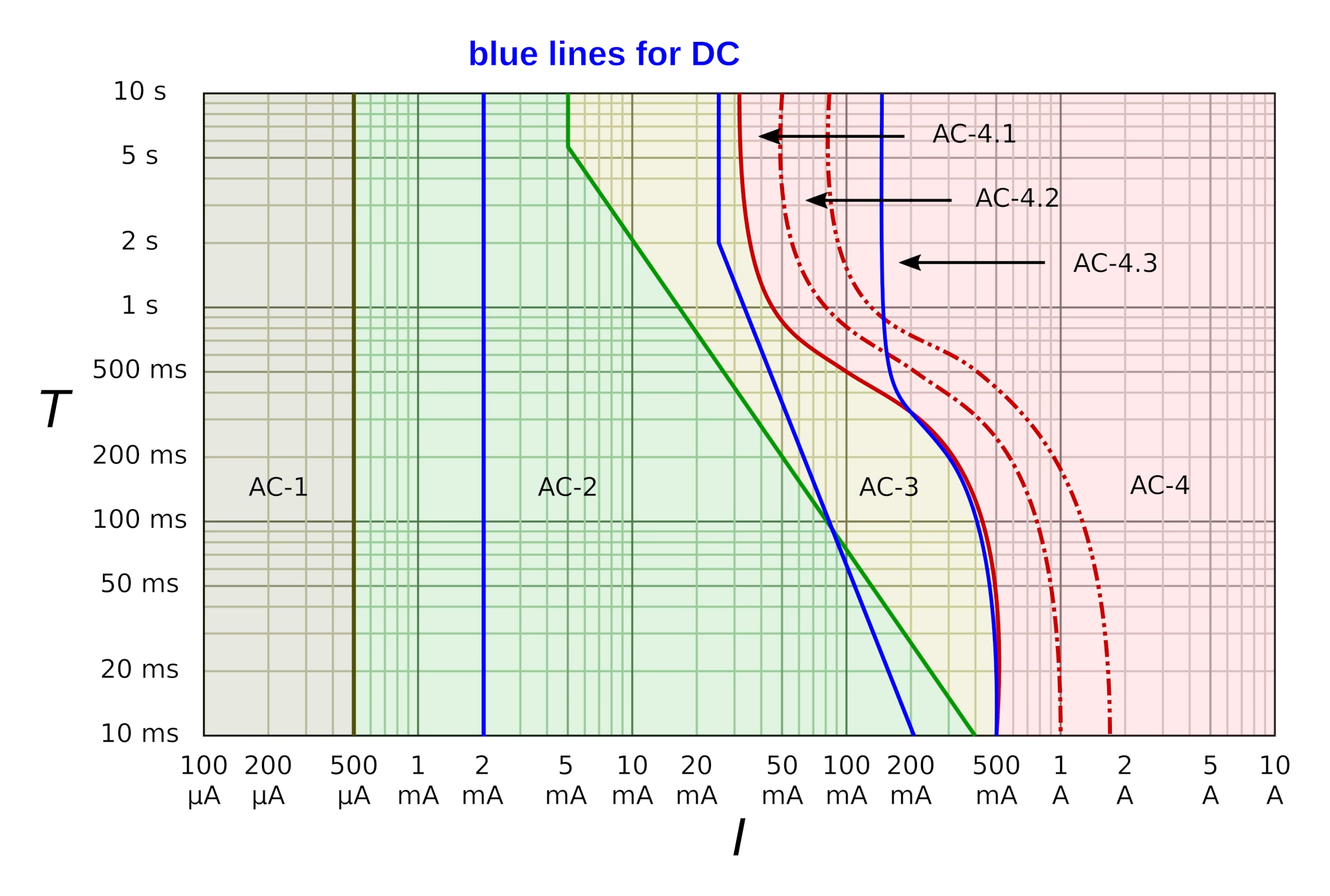
    [17] Differences in electrical stimulation thresholds between men and women https://onlinelibrary.wiley.com/doi/10.1002/ana.21346
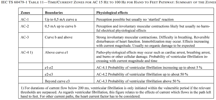
    [18] J. C. Keesey, F.S. Letcher. “Human Thresholds of Electric Shock at Power Transmission Frequencies.” Arch. Env. Health. Vol. 21. 1970. Available: https://zoryglaser.com/wp-content/uploads/2020/05/HUMAN-THRESHOLD-OF-ELECTRIC-SHOCK-AT-POWER-TRANSMISSION-FREQUENCIES.pdf [Accessed 2025-11-30]
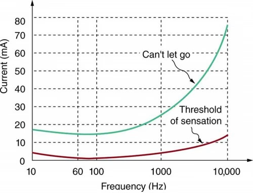
    [19] Minimum Thresholds for Physiological Responses to Flow of Alternating Electric Current Through the Human Body at Power-Transmission Frequencies, Naval Medical Research Institute. 1969. Available: https://zoryglaser.com/wp-content/uploads/2020/05/MINIMUM-THRESHOLDS-FOR-PHYSIOLOGICAL-RESPONSES-TO-FLOW-OF-ALTERNATING-ELECTRIC-CURRENT-THROUGH-THE-HUMAN-BODY-AT-POWER-TRANSMISSION-FREQUENCIES-NMRI.pdf [Accessed: 2025-11-30]
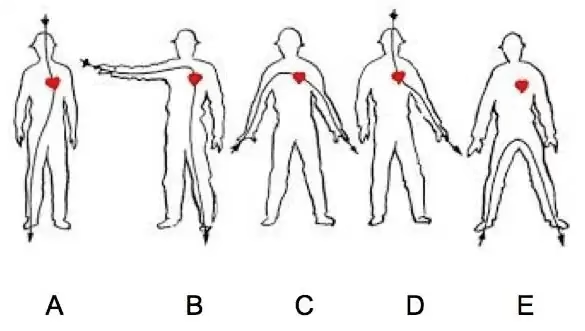
    [20] Safe Levels of Current in the Human Body Available: https://www.d.umn.edu/~sburns/EE2212/L-Safe-Levels-of-Current-in-the-Human-Body.pdf [Accessed 2025-11-30]

    [21] Sex and age differences in sensory threshold for … Available: https://www.scielo.br/j/fm/a/FkPdhzvxmxLcZ7QXjsjCGLz/?format=pdf&lang=en [Accessed 2025-11-30]

    [22] Differences in electrical stimulation thresholds between … Available: https://onlinelibrary.wiley.com/doi/abs/10.1002/ana.21346 [Accessed 2025-11-30]

    [23] Let Go Current | IE Rule – Estimation and Costing Available: https://www.electricalje.com/2024/12/let-go-current-ie-rule-estimation-and.html [Accessed 2025-11-30]

    [24] “Gender Differences in Current Received during Transcranial Electrical Stimulation”. Frontiers. Available: https://www.frontiersin.org/journals/psychiatry/articles/10.3389/fpsyt.2014.00104/full [Accessed 2025-11-30]

    [25] “HUMAN RESPONSES TO ELECTRICITY “. Available: https://ntrs.nasa.gov/api/citations/19730001338/downloads/19730001338.pdf [Accessed 2025-11-30]

    [26] “Factors Affecting and Adjustments for Sex Differences in Current Perception Threshold With Transcutaneous Electrical Stimulation in Healthy Subjects”. Available: https://onlinelibrary.wiley.com/doi/full/10.1111/ner.12889 [Accessed 2025-11-30]

    [27] “The effects of high electric current on the human body”. Available: https://betacomearthing.com/resources/the-effects-of-high-electric-current-on-the-human-body/ [Accessed 2025-11-30]

    [28] E. Dölker, S. Lau, M. A. Bernhard, J. Haueisen. “Perception thresholds and qualitative perceptions for electrocutaneous stimulation”. Available: https://pmc.ncbi.nlm.nih.gov/articles/PMC9072403/ [Accessed 2025-11-30]

    [29] “AC & DC Electric Shocks – Electrical Energy in the Home”. Available: https://eliotsphysics.weebly.com/ac–dc-electric-shocks.html [Accessed 2025-11-30]

    [30] S. Seno, H. Shimazu, E. Kogure, A. Watanabe, H. Kobayashi. “Factors Affecting and Adjustments for Sex Differences in Current Perception Threshold With Transcutaneous Electrical Stimulation in Healthy Subjects”. Available: https://pmc.ncbi.nlm.nih.gov/articles/PMC6766980/ [Accessed 2025-11-30]

    [31] I. Lund, T. Lundeberg, J. Kowalski, L. Svensson. “Gender differences in electrical pain threshold responses to transcutaneous electrical nerve stimulation (TENS)”. Available: https://pubmed.ncbi.nlm.nih.gov/15670645/ [Accessed 2025-11-30]

    [32] “Characteristics of current perception produced by intermediate-frequency contact currents in healthy adults”. Frontiers. Available: https://www.frontiersin.org/journals/neuroscience/articles/10.3389/fnins.2023.1145505/full [Accessed 2025-11-30]

    [33] ‘Limits of Human Exposure to Radiofrequency Electromagnetic Fields in the Frequency Range from 3 kHz to 300 GHz’. Ottawa: Health Canada. 2015. Available: https://www.canada.ca/content/dam/hc-sc/migration/hc-sc/ewh-semt/alt_formats/pdf/consult/_2014/safety_code_6-code_securite_6/final-finale-eng.pdf [Accessed: 2025-12-01]

    [34] ‘Guidelines for Limiting Exposure to Electromagnetic Fields (100 kHz to 300 GHz)’, Health Physics, vol. 118, no. 5, pp. 483–524, May 2020, doi: 10.1097/HP.0000000000001210. Available: https://www.icnirp.org/cms/upload/publications/ICNIRPrfgdl2020.pdf [Accessed: 2025-12-31]