Last updated on 2025-11-07 at 11:36 EST (UTC-05:00)
Understanding Antennas: From Theory to the Sky
This week in the RAC Amateur Radio course, we dug into one of the most fundamental — and fascinating — parts of radio communication: antennas. For many hams, the antenna is both the most visible and most mysterious part of the station.
It’s easy to get lost in the jargon of impedance, resonance, and reactance, but at its heart, an antenna is simply the bridge between the electrical energy flowing in our wires and the electromagnetic waves travelling through the air.
What an Antenna Really Does
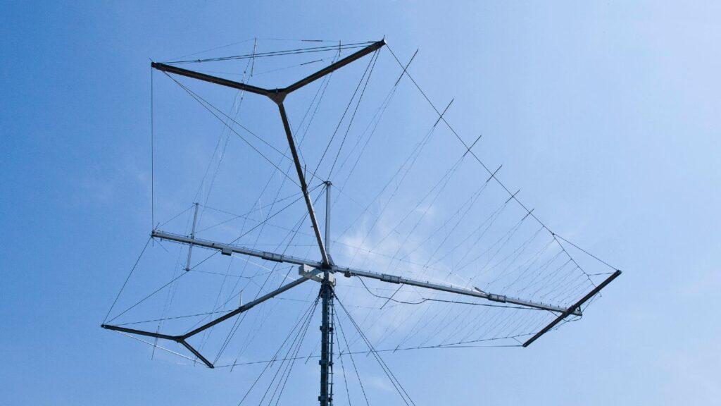
image: Rohde & Schwartz
An antenna isn’t just a piece of wire hung in the air (although it might be in the strictest sense!). It’s an energy converter. When transmitting, it takes the alternating current from the transmitter and radiates it as electromagnetic waves. When receiving, it does the reverse — capturing energy from those same waves and inducing a tiny voltage that a receiver can amplify into something meaningful.
Al Penny’s lecture [1] emphasized that every antenna, no matter how simple, has both resistive and reactive components to its impedance. A perfectly resonant antenna is one where those reactive elements — the capacitive and inductive parts — cancel each other out, leaving only the resistive component. That’s the sweet spot, where power transfer between the transmitter and the antenna is most efficient.
How Antennas Transmit and Receive Radio Waves
Antenna theory can get pretty deep pretty quickly, but at its core, it’s all about moving energy between two domains — the electrical world of circuits and the electromagnetic world that fills the space around us. When a transmitter drives alternating current into an antenna, electrons surge back and forth along its conductors. Every time those electrons accelerate or decelerate, they disturb the surrounding electric and magnetic fields.
A transmitting antenna
By Chetvorno – Own work, CC0, Link
The animation above shows what’s happening around a dipole antenna when it’s transmitting. In the centre of the image are the two antenna elements, the dipole’s metal rods. Alternating current from a radio transmitter flows up and down through those rods, creating standing waves of current and voltage, shown by the small red arrows.
As the voltage reverses polarity, the surrounding electric field expands, collapses, and reverses direction. Near the antenna, the field lines (shown in black) are tightly curved, linking the positive and negative ends. But as the cycle continues, those field loops pinch off, detach, and travel outward through space at the speed of light — that’s the radio wave being launched [2].
Those disturbances don’t just stay near the antenna — they radiate outward as electromagnetic waves, carrying energy and information into space. That’s how an antenna “launches” a radio wave.
You’ll notice that most of the energy radiates out sideways, perpendicular to the antenna, and very little travels straight up or down along the antenna’s axis. The pattern is symmetrical all around the dipole, forming a doughnut-shaped radiation field. The animation runs at a vastly slowed-down rate — in reality, these field reversals happen millions or even billions of times per second.
Even in this simplified view, it’s a beautiful illustration of how alternating current in a simple conductor creates electromagnetic waves that carry information through space.
A receiving antenna
Flip the process around and you have a receiving antenna. As a radio wave passes through space, its oscillating electric field pushes and pulls on the electrons in the antenna’s metal. The motion of those electrons creates a tiny alternating voltage that mirrors the original transmitted signal. The receiver then amplifies and processes that voltage to recover the sound, data, or other information that was encoded in the radio wave. [2]
By Chetvorno – Own work, CC0, https://commons.wikimedia.org/w/index.php?curid=149776956
In both directions, the antenna acts as a translator — turning electrical motion into electromagnetic radiation, and then back again. It’s a beautifully simple concept that underpins everything from AM broadcast radio to satellite communication. Once you understand that relationship between current flow and radiated field, you’ve grasped the essential physics of how radio truly works.
Why Antenna Size and Wavelength Matter
Almost anything can act as an antenna. The more conductive the material, the more effective an antenna it can become. Radio signals can be picked up on a random length of wire.
But an antenna doesn’t just need to exist — it needs to be the right size for the signal it’s handling. Radio waves have wavelengths that can range from millimetres to kilometres, and an antenna works most efficiently when its physical length corresponds to a simple fraction of that wavelength. That’s because the alternating current driving the antenna sets up standing waves along its structure. When the length of the antenna aligns with the wavelength — say, a half-wave or quarter-wave — those standing waves reinforce the radiation instead of cancelling it. The result is a strong, efficient transfer of energy into (or out of) the surrounding space.
This resonance principle is why an FM antenna on your car is about 75 cm long — half the wavelength of a 100 MHz signal. The same physics applies to every part of the spectrum, whether it’s a handheld VHF transceiver, a Wi-Fi router, or a shortwave dipole stretched between two trees. If the antenna is too short or too long for the wavelength, it won’t efficiently launch or capture radio waves. Some of the transmitter’s energy simply reflects back into the circuit as standing waves, and the received signal strength drops.
Once you start noticing the relationship between wavelength and antenna length, you see it everywhere: the whip on a police cruiser, the loop in a pocket radio, even the hidden traces printed on your phone’s circuit board. They’re all just different expressions of the same idea — tuning a piece of metal to resonate with a particular frequency so it can speak the language of radio.
Matching and Efficiency
A big takeaway was that antennas don’t have to be perfectly resonant to perform well — but understanding impedance matching makes all the difference. When the feedline and antenna impedance are mismatched, some of the transmitted power is reflected back down the line instead of radiating outward. At HF frequencies, these losses are minor; at VHF and higher frequencies, they can become significant.
Efficiency also comes down to losses — in the conductors themselves and in the surrounding environment. Skin effect, ground loss, and nearby conductive materials can all sap power that should be radiated as a useful signal. Using good-quality materials, keeping connections clean, and situating the antenna away from large conductive structures are all small details that make measurable differences.
The Magic of the Dipole
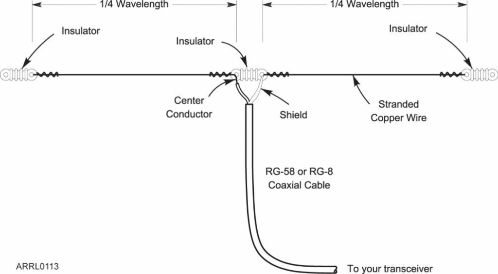
image: Amateur Radio Relay League
We spent time looking at the humble dipole, the classic half-wave antenna that nearly every amateur builds first. It’s simple, predictable, and a great reference point for understanding how antennas behave. The presentation illustrated how current and voltage vary along its length — maximum current and minimum voltage at the centre, and the reverse at the ends.
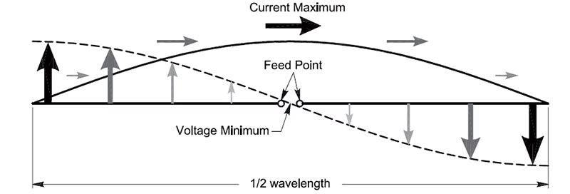
image:Amateur Radio Relay League
Height above ground plays a major role in how a dipole radiates. Too low, and much of the signal goes straight up — an NVIS (Near Vertical Incidence Skywave) pattern useful for regional communication but not long-distance (DX) communication. Raise it higher, and the angle of radiation lowers, extending your reach across continents. As a rule of thumb, doubling the height of a horizontal antenna can yield about a 6 dB gain — roughly equivalent to quadrupling your transmitter power.
Radiation resistance
What’s Going On in an Antenna
When alternating current (AC) flows in an antenna, the electrons in the conductors move back and forth — speeding up, slowing down, and reversing direction in time with the signal frequency. Any time a charged particle accelerates (changes speed or direction), it gives off electromagnetic radiation — radio waves in this case.
Radiation Takes Energy Away
Those radio waves carry energy and momentum away from the antenna. Think of it like throwing pebbles into a pond — each ripple carries away a little of the energy from your hand.
When electrons in the antenna create these waves, they lose a bit of their own energy and momentum each time. This effect is called the radiation reaction — the reaction force on the electrons due to the momentum they’ve given to the outgoing waves.
How That Looks Electrically
From the transmitter’s point of view, this energy loss looks like a resistance — a place where energy is being “used up.” However, unlike heat loss in a resistor (which converts energy into heat), this “radiation resistance” converts electrical energy into electromagnetic waves that radiate from the antenna.
So:
- The transmitter sends current into the antenna.
- Part of that energy radiates into space (useful radiation).
- The rest might be lost as heat in the metal or the ground.
- The energy radiated shows up in circuit terms as a voltage drop — that’s the radiation resistance.
Why It Matters
The radiation resistance is what allows power to leave the transmitter and be converted into radio waves. It’s a real, physical effect — not just theoretical.
If an antenna had no radiation resistance, it wouldn’t radiate; if it had only loss resistance, it would just heat up.
Mathematically, we can express the power dissipated in the antenna as

Where:
Pa is the power dissipated in the antenna
I is the current in the antenna
R0 is the radiation resistance
R is the resistance of the antenna conductors
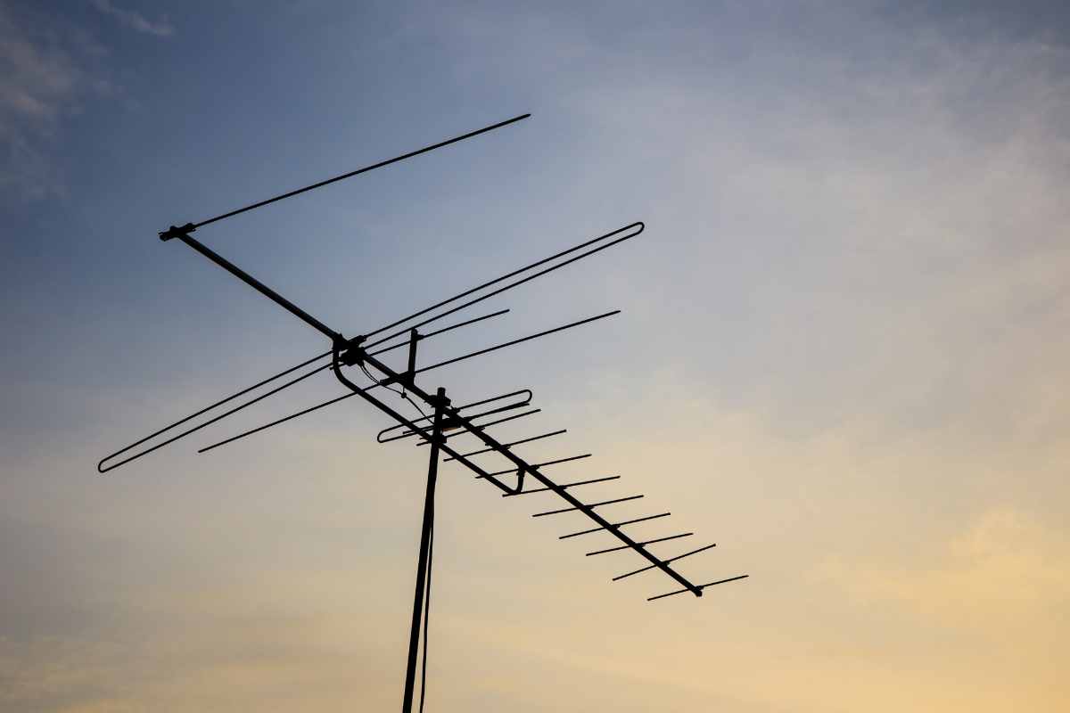
Radiation Patterns and Directivity
Another concept that stood out was directivity — how antennas focus energy in some directions more than others. The presentation used the analogy of a flashlight beam: a simple way to visualize gain and radiation patterns. A theoretical isotropic radiator would spread energy equally in all directions, but real antennas, like dipoles and Yagis, concentrate it to improve performance in desired directions.
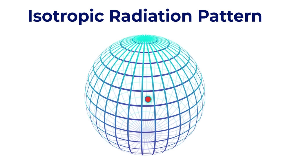
image: Ham Radio Prep [4]
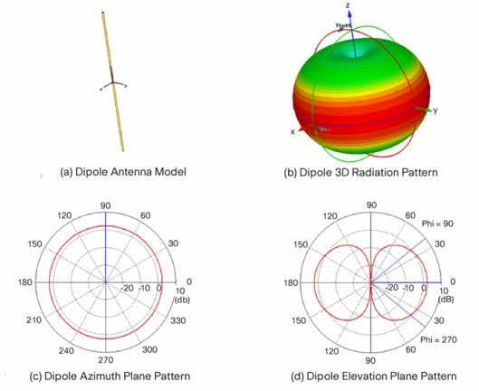
image: RAYmaps [5]
That directivity is what makes beam antennas such powerful tools for both transmitting and receiving. By focusing energy in one direction, you increase your effective radiated power (ERP) without increasing transmitter output.
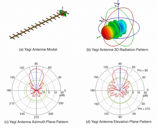
image: RAYmaps [6]
NVIS and the Beauty of Short-Range Skywave
One of the most fascinating parts of the lesson was Near Vertical Incidence Skywave (NVIS) propagation — a mode that’s perfect for communicating within a few hundred kilometres. By using a horizontally polarized antenna just a fraction of a wavelength above ground (around 0.2 to 0.25 λ), signals are sent almost straight up, then refracted back down by the ionosphere to cover the surrounding region.
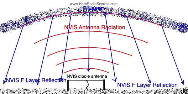
image: hamradiosecrets.com [7]
This is the perfect technique for emergency communications or connecting stations in rugged or forested terrain where line-of-sight VHF isn’t practical. Antennas for NVIS use are simple to build and remarkably effective once you understand their geometry and limitations.
Looking Up
The more I study antennas, the more I appreciate the blend of art, science, and practical engineering that goes into them. They’re one of the purest expressions of applied physics in radio — translating invisible electric fields into something that connects people across towns, continents, and even into space.
It’s a reminder that while technology evolves — from spark-gap transmitters to software-defined radios — the fundamentals of electromagnetism haven’t changed since Maxwell first put pen to paper. Every signal still begins with an oscillating current in a piece of wire, reaching out to find another somewhere in the noise.
Sources
[1] A. Penney, ‘Antennas: Chapter 8A’, Jun. 07, 2024.
[2] ‘Antenna (radio)’, Wikipedia. Oct. 17, 2025. Accessed: Oct. 26, 2025. [Online]. Available: https://en.wikipedia.org/w/index.php?title=Antenna_(radio)&oldid=1317274066
[3] ‘As an antenna expert, I’ll explain how antennas work’, Antenna Fix. Accessed: Oct. 21, 2025. [Online]. Available: https://antennafix.com/how-do-antenna-work/
[4] ‘Lesson 27’, Ham Radio Prep. Accessed: Oct. 22, 2025. [Online]. Available: https://hamradioprep.com/courseid-6/27/
[5] Y. Ahmed, ‘Dipole Antenna 3D Radiation Pattern – RAYmaps’, RAYmaps. Accessed: Oct. 22, 2025. [Online]. Available: https://www.raymaps.com/index.php/some-common-antenna-radiation-patterns/dipole-3d-radiation-pattern/
[6] Y. Ahmed, ‘Yagi Antenna 3D Radiation Pattern – RAYmaps’, RAYmaps. Accessed: Oct. 22, 2025. [Online]. Available: https://www.raymaps.com/index.php/some-common-antenna-radiation-patterns/yagi-antenna-3d-radiation-pattern/
[7] C. Jollet, ‘Portable Linear-Loaded NVIS Antenna for 40 Meters’, Ham Radio Secrets. Accessed: Oct. 22, 2025. [Online]. Available: https://www.hamradiosecrets.com/nvis-antenna.html
Leave a Reply