From Resistance to Reflection: Understanding Transmission Lines
This week’s class dove into one of the most practical — and at times puzzling — parts of radio work: transmission lines.
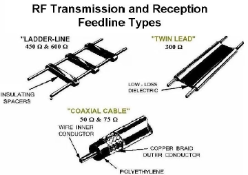
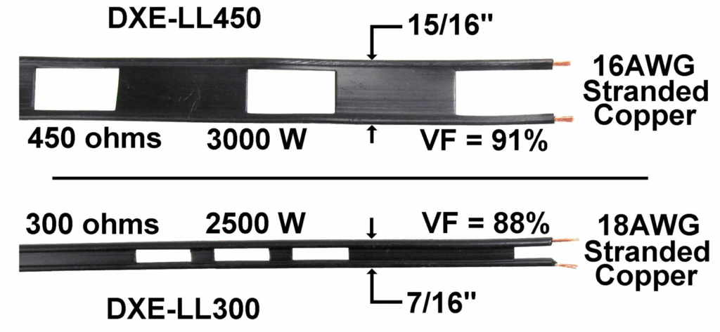
image: DXEngineering
At first glance, feedlines might seem like nothing more than fancy electrical cables, but as we learned, at radio frequencies the story changes completely. A transmission line isn’t just a wire — it’s a carefully balanced system that has to guide alternating current at very high frequencies, where even a few centimetres of cable can become a significant part of a wavelength.
The Invisible Highway Between Radio and Antenna
Our radios don’t magically send energy into space. The power has to travel along a transmission line — the “highway” between the transceiver and the antenna. But unlike ordinary power cords, transmission lines must manage reflections, impedance, and losses that don’t exist (or don’t matter) at lower frequencies.
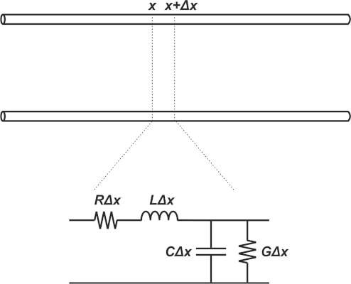
Here, R and G represent, respectively, the resistance per unit length of the wire and the conductance per unit length of the dielectric that separates the conductors. L and C represent the inductance and capacitance per unit length of the transmission line.
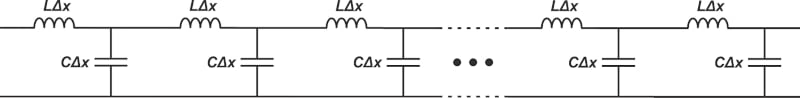
At radio frequencies, the series reactance is usually much greater than the series resistance, and the shunt reactance is usually much less than the shunt resistance, so we can assume that both resistances can be neglected. Neglecting R and G components, a lossless transmission line can be modelled by the infinite ladder network shown below.
That’s where characteristic impedance comes in. Every transmission line — whether it’s open-wire, twin-lead, or coaxial — has a natural impedance determined by its geometry and materials. Keep everything matched, and your power flows smoothly. Get it wrong, and some of that power comes screaming back down the line as reflected energy, forming standing waves.
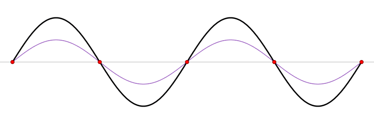
When a continuous signal travels through a transmission line and encounters a load with a mismatched impedance, part of that signal reflects back toward the source. The original (incident) wave and the reflected wave move in opposite directions, and when they interact, they create interference — a standing wave. This standing wave is a real, physical effect along the cable’s length, producing points where the signal’s amplitude peaks and others where it dips. In some cases, the voltage at these peaks can exceed the original signal’s voltage, potentially leading to overheating or even damage to cables and components.
The AT&T archive video above effectively explains wave behaviour, impedance mismatches, reflections, and standing waves. It’s definitely worth watching if you want to gain a better understanding of waves and how they behave.
Skin Effect
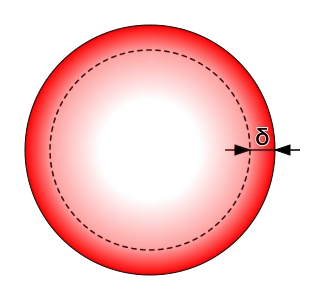
The skin effect is the tendency of alternating current (AC) to flow primarily near the surface of a conductor rather than evenly through its entire cross-section. As frequency increases, the current becomes increasingly confined to a thin outer layer of the conductor.
This behaviour occurs because the alternating magnetic field generated by AC induces eddy currents within the conductor. These opposing currents restrict the flow of current toward the surface, resulting in a non-uniform current density. The depth to which the current penetrates is referred to as the skin depth (δ).
Biezl, Public domain, via Wikimedia Commons
What Determines Skin Depth?
Skin depth depends on both the frequency of the alternating current and the electrical and magnetic properties of the conductor. It is defined as the depth at which current density falls to 1/e (approximately 37%) of its surface value.
As frequency increases, the skin depth decreases, meaning the current is confined to a thinner surface layer. This reduces the effective cross-sectional area available for current flow and increases the conductor’s effective resistance.
By Biezl – Own work, Public Domain, Link
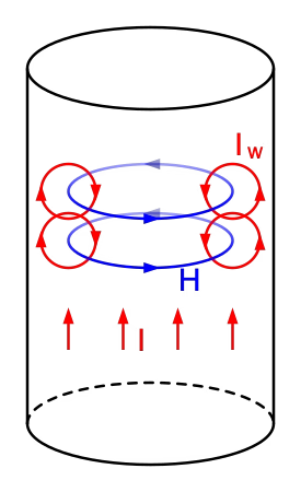
A main current I flowing through a conductor induces a magnetic field H. If the current increases, as in this figure, the resulting rise in H induces separate, circulating eddy currents IW, which partially cancel the current flow in the center and reinforce it near the skin.
For example, in copper at 60 Hz, the skin depth is about 8.5 mm. At higher frequencies—such as in radio or high-frequency switching circuits—it becomes much smaller, sometimes only a fraction of a millimetre.
Why It Matters
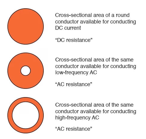
Because AC current tends to crowd toward the surface, less of the conductor is effectively carrying current. The result is a smaller conducting area, resulting in greater resistance than with direct current (DC).
At low frequencies, this effect is minimal; however, as the frequency rises, engineers must account for the skin effect when designing busbars, transformer windings, RF components, and high-frequency power systems to ensure optimal efficiency and thermal performance.
Balanced vs Unbalanced — and Why It Matters
One of the biggest conceptual takeaways was the difference between balanced and unbalanced lines.
- Balanced lines — like ladder line or open-wire feeders — carry equal and opposite currents, cancelling their electromagnetic fields and minimizing radiation from the line itself. They’re remarkably efficient and forgiving of mismatch losses, but they demand careful installation: constant spacing, no nearby metal, and protection from rain and ice.
- Unbalanced lines, primarily coaxial cables, put one conductor at ground potential and carry RF on the inner conductor. They’re rugged, weather-resistant, and far easier to route through walls and towers — which is why almost every modern ham shack uses them. The trade-off is higher loss, especially at VHF and UHF, and the ever-present danger of water ingress if you neglect proper sealing.
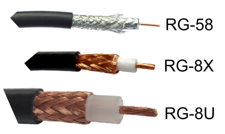
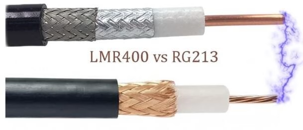
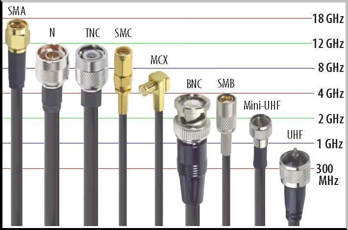
Coax Choices and Connectors
We also looked at the “alphabet soup” of coax cables — RG-58, RG-8, RG-213, LMR-400, and others. The takeaway is that cable choice is all about loss versus flexibility. Smaller, flexible cables like RG-58 are fine for short HF runs, but not for long VHF or UHF feeds. Heavier cables or low-loss hardline types deliver more power with less attenuation, but are expensive and stiff.
Even connectors matter. The classic PL-259/SO-239 “UHF” connector still dominates HF rigs, though it’s really only suited for the lower frequencies. Higher-frequency work calls for N-type or SMA connectors, each designed to maintain consistent impedance at GHz ranges.
| Connector Type | Plug (Male) | Jack (Female) |
| Type N | 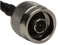 (pin with threads inside) (pin with threads inside) | 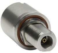 (socket with threads outside) (socket with threads outside) |
| UHF (PL259) | 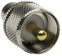 (pin with threads inside) (pin with threads inside) | 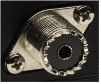 (socket with threads outside) (socket with threads outside) |
| TNC | 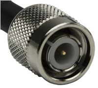 (pin with threads inside) (pin with threads inside) | 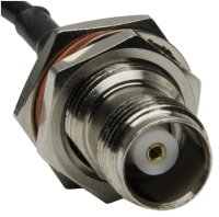 (socket with threads outside) (socket with threads outside) |
| Reverse Polarity TNC (RPTNC) | 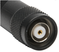 (socket with threads inside) (socket with threads inside) | 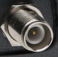 (pin with threads outside) (pin with threads outside) |
| BNC | 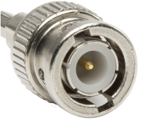 (pin with threads inside) (pin with threads inside) | 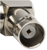 (socket with threads outside) (socket with threads outside) |
| SMA | 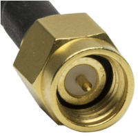 (pin with threads inside) (pin with threads inside) | 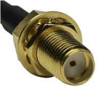 (socket with threads outside) (socket with threads outside) |
| Reverse Polarity SMA (RPSMA) | 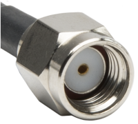 (socket with threads inside) (socket with threads inside) | 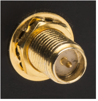 (pin with threads outside) (pin with threads outside) |
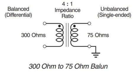
The Role of the Balun
Balanced antennas like dipoles don’t always play nicely with unbalanced coax, and that’s where baluns (balanced-to-unbalanced transformers) come in. A simple choke balun — just a coil of coax at the feedpoint — can stop unwanted current from creeping down the outside of your shield. More sophisticated transformer baluns use ferrite cores to match impedances and isolate circuits. It’s a brilliant bit of engineering simplicity that can make or break an antenna system.
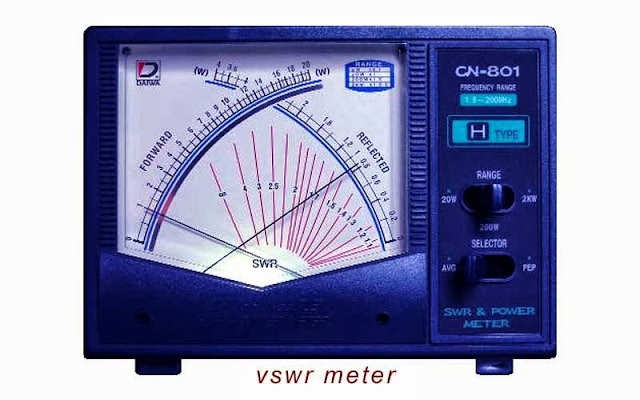
When the Waves Stand Still
Finally, we explored VSWR — Voltage Standing Wave Ratio. In theory, a perfect match between radio, cable, and antenna gives a 1:1 ratio. In reality, a little reflection is normal — a VSWR of 2:1 is fine, but 5:1 means you’ve got work to do. Watching those peaks and valleys on a scope or analyzer really drives home how reflections eat power and distort performance.
Looking Ahead
This chapter was a solid reminder that the magic of radio isn’t just in the airwaves — it’s in the copper, dielectric, and geometry of the cables that connect everything together. Transmission lines are the quiet heroes of every ham station: invisible when they work right, painfully obvious when they don’t.
Sources
[1] A. Penney, ‘Transmission Lines’, Online, Oct. 23, 2025.
[2] S. Arar, ‘RF Design Basics—Introduction to Transmission Lines’, All About Circuits. Accessed: Oct. 19, 2025. [Online]. Available: https://www.allaboutcircuits.com/technical-articles/basic-concepts-in-rf-design-introduction-to-transmission-lines/
[3] ‘What Is the Skin Effect?’